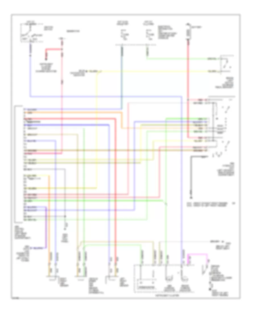
AIR CONDITIONING
Air Conditioning Wiring Diagrams for Volvo 940 Turbo 1995
 https://portal-diagnostov.com/license.html
Automotive Electricians Portal FZCO
Automotive Electricians Portal FZCO
https://portal-diagnostov.com/license.html
https://portal-diagnostov.com/license.html
Automotive Electricians Portal FZCO
Automotive Electricians Portal FZCO
List of elements for Air Conditioning Wiring Diagrams for Volvo 940 Turbo 1995:
- (right kick panel)
- A/c compressor
- A/c controls (center of i/p)
- A/c high pressure sensor (behind center
- A/c low pressure sensor (on accumulator)
- C 1995 vftc
- Cabin fan motor
- Cabin fan resistors
- Charging system (generator)
- Engine cooling fan
- Engine cooling fan relay (top of radiator)
- Fuse 11-16 30a
- Fuse block
- Fusible link
- G101 (right front fender)
- G203
- Heater control switch
- High speed pressure sensor (front of radiator)
- Hot at all times
- Hot in on
- Interior lights system
- Lh-jetronic 2.4 (mfi) system control module (behind right kick panel)
- Low speed pressure sensor (front of radiator)
- Mcc servo motor (behind right side of i/p)
- Of front bumper)
- Red
ANTI-LOCK BRAKES
Anti-lock Brake Wiring Diagrams for Volvo 940 Turbo 1995
List of elements for Anti-lock Brake Wiring Diagrams for Volvo 940 Turbo 1995:
- (below left front seat)
- (front of right front fender) (front of left front fender)
- Abs control module (left rear of engine compartment)
- Abs hydraulic unit (left (or right) side of engine compartment)
- Abs warning indicator
- Accy
- Battery
- Brake fluid level sensor (on brake master cylinder reservoir)
- Brake light switch (on brake pedal bracket)
- Brake warning indicator
- Bulb malfunction indicator
- Electrical distribution unit (center of dash under center console)
- Fuse 15a
- G101 g100
- G200 (left kick panel)
- G300
- Generator
- Hot at all times
- Hot in on and start
- Ignition switch
- Instrument cluster
- Instrument cluster system (charge indicator)
- Left front abs sensor
- Nca
- Obd data link connector (front of left strut tower)
- Off
- Pnk
- Red
- Right front abs sensor
- Run
- Speedometer
- Start
- Vehicle speed and abs sensor (at rear differential)
ANTI-THEFT
Anti-theft Wiring Diagram for Volvo 940 Turbo 1995
List of elements for Anti-theft Wiring Diagram for Volvo 940 Turbo 1995:
- 15 rail
- Anti-theft alarm connector #1 (at steering column)
- Anti-theft alarm connector #2 (at steering column)
- Anti-theft alarm connector #3 (left front of engine compt)
- Central locking relay
- Electrical distribution unit (center of dash, under center console)
- Exterior lights system
- Fuse 15a
- Fuse 25a
- G203 (right kick panel)
- G407 (left rear of trunk)
- Ground connector rail (in electrical distribution unit)
- Hot at all times
- Hot in run or start
- Left front door switch
- Left rear door switch
- Load area roof light
- Lock
- Lock button switch
- Red
- Right front door switch
- Right rear door switch
- Sedan
- Tailgate door switch
- Tailgate lock unit
- Trunk light
- Unlock
- Wagon
COMPUTER DATA LINES
Computer Data Lines for Volvo 940 Turbo 1995
List of elements for Computer Data Lines for Volvo 940 Turbo 1995:
- (front of left front fender)
- Abs control module (left side of i/p)
- Acc
- Cruise control module (left kick panel)
- Driver's seat control module (w/ memory seats) (left front seat frame)
- Egr converter (near left front shock tower)
- Electrical distribution unit (center of dash, under center console)
- Ez-k (di) system control module (left side of i/p)
- Ez-k (di) system power amplifier (left front fender)
- G100
- Hot at all times
- Ignition switch
- Lh-jetronic system control module (right kick panel)
- Obd data link connector (left rear of engine compt)
- Off
- Run
- Srs sensor module (under left front seat)
- Start
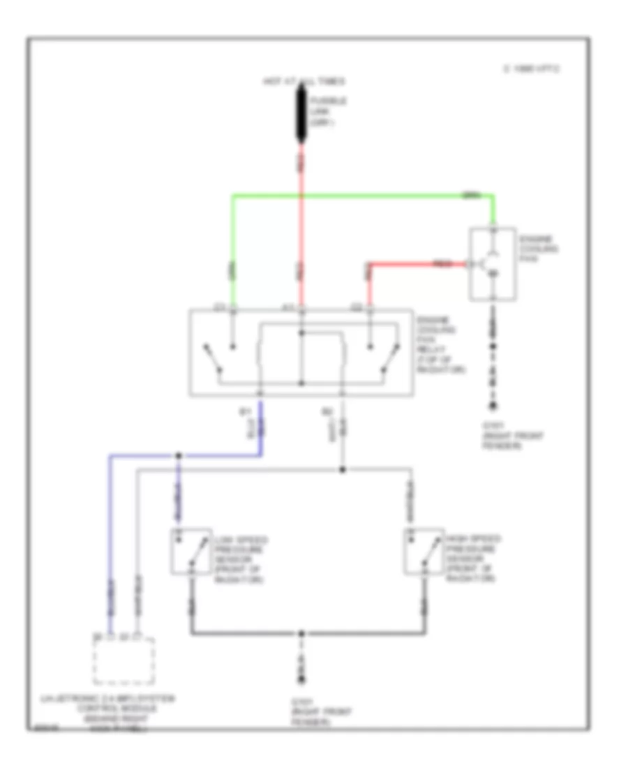
COOLING FAN
Cooling Fan Wiring Diagram for Volvo 940 Turbo 1995
List of elements for Cooling Fan Wiring Diagram for Volvo 940 Turbo 1995:
- (behind right
- C 1995 vftc
- Control module
- Engine cooling fan
- Engine cooling fan relay (top of radiator)
- Fusible link
- G101 (right front fender)
- High speed pressure sensor (front of radiator)
- Hot at all times
- Kick panel)
- Lh-jetronic 2.4 (mfi) system
- Low speed pressure sensor (front of radiator)
- Red
CRUISE CONTROL
Cruise Control Wiring Diagram for Volvo 940 Turbo 1995
List of elements for Cruise Control Wiring Diagram for Volvo 940 Turbo 1995:
- (brake pedal bracket)
- Acc
- Anti-lock brakes system (abs control module)
- Brake light switch (above brake pedal)
- Brake pedal switch
- Bulb malfunction indicator
- Cruise control module (left kick panel)
- Cruise control switch
- Cruise control vacuum pump (near left front shock tower)
- Electrical distribution unit (center of dash, under center console)
- Fuse 15a
- G300 (below left front seat)
- Hot at all times
- Hot in run
- Ignition switch
- Instrument cluster
- Obd data link connector (at left front shock tower)
- Off
- Or start
- Pnk
- Res
- Run
- Set
- Speedometer
- Start
DEFOGGERS
Defogger Wiring Diagram for Volvo 940 Turbo 1995
List of elements for Defogger Wiring Diagram for Volvo 940 Turbo 1995:
- 15i
- Electrical distribution unit (center of dash, under center console)
- Fuse 30a
- G203 (right kick panel)
- G404 (left taillight assembly)
- G905 (top of right c pillar)
- Ground connection rail (electrical distribution unit)
- Heated rear window
- Heated rear window switch
- Hot in run
- Indicator
- Sedan
- Wagon
Rear Defogger & Heated Mirrors Wiring Diagram for Volvo 940 Turbo 1995
List of elements for Rear Defogger & Heated Mirrors Wiring Diagram for Volvo 940 Turbo 1995:
- (top of right "c" pillar)
- 15i
- 87b
- Electrical distribution unit (center of dash, under center console)
- Fuse 30a
- G203 (right kick panel)
- G404 (left taillight assembly)
- G905
- Ground connection rail (electrical distribution unit)
- Heated rear window
- Heated rear window/ door mirrors switch
- Heating element
- Hot in run
- Left power door mirror
- Right power door mirror
- Sedan
- Wagon
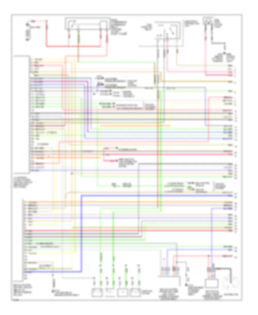
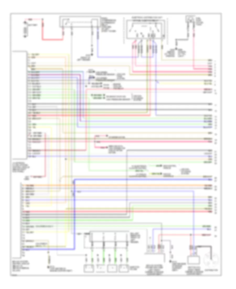
ENGINE PERFORMANCE
2.3L
2.3L Non-Turbo, Engine Performance Wiring Diagrams (1 of 2) for Volvo 940 Turbo 1995
List of elements for 2.3L Non-Turbo, Engine Performance Wiring Diagrams (1 of 2) for Volvo 940 Turbo 1995:
- (a/t only)
- (below i/p, above steering column)
- (california only)
- (w/ b230fd)
- (w/ b230g)
- (w/ egr, b230fd)
- Air con- ditioning system
- Battery
- Cooling fans system
- Distributor
- Ecc control module
- Electrical distribution unit
- Engine cooling fan relay
- Ez-k (di) system control module
- Ez-k (di) system power amplifier (left front corner of engine compartment)
- Fuel injection relay
- Fuel pump (in fuel tank)
- G112 (top center of engine compartment)
- G115 (center rear of engine compart- ment)
- G408 (sedan) (at trunk opening)
- G999 (wagon) (at tail light)
- High pressure sensor
- High-speed pressure sensor
- Ignition coil (right rear corner of engine compartment)
- Injection valves
- Lh-jetronic 2.4 (mfi) system control module (behind right kick panel)
- Low-speed pressure sensor
- Mcc a/c controls
- Nca
- Pin b1
- Pin b2
- Pnk
- Radio interference suppression relay (forward of left strut tower)
- Red
- Service data link connector (for starter motor)
- Solenoid coupling
- Starter motor
- W/ electronic climate control
- W/ manual climate control
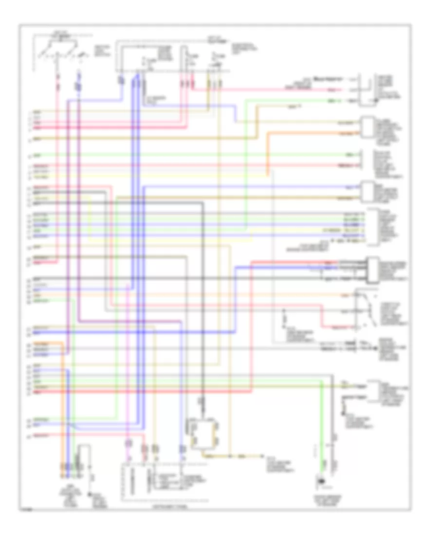
2.3L Non-Turbo, Engine Performance Wiring Diagrams (2 of 2) for Volvo 940 Turbo 1995
List of elements for 2.3L Non-Turbo, Engine Performance Wiring Diagrams (2 of 2) for Volvo 940 Turbo 1995:
- (w/ b230fd only)
- (w/ b230g)
- A/t
- A13
- Combined instrument fuse
- Egr converter (california) (left strut tower)
- Egr temperature sensor (california) (left front of engine)
- Electrical distribution unit
- Engine coolant temperature sensor (left side of engine)
- Engine speed (rpm) sensor (rear of engine compartment)
- Fuse 15a
- Fuse 25a
- G100 (front of left fender)
- G101 (front of right fender)
- G112 (top center of engine compartment)
- G115 (center rear of engine compartment)
- Heated oxygen sensor (at catalytic converter)
- Hot at all times
- Idle air control valve (top left center of engine compartment)
- Ignition lock (switch)
- Iii
- Instrument panel
- Knock sensor (on left side of engine)
- M/t
- Malfunc- tion indicator lamp
- Mass air flow sensor (left side of engine compart- ment)
- Nca
- Obd data link connector (left strut tower)
- Pnk
- Power distri- bution system
- Pulsed secondary air injection solenoid (w/ b230fd) (left strut tower)
- Red
- Speedometer
- Tachometer
- Throttle position switch (left rear of engine compartment)
2.3L Turbo, Engine Performance Wiring Diagrams (1 of 2) for Volvo 940 Turbo 1995
List of elements for 2.3L Turbo, Engine Performance Wiring Diagrams (1 of 2) for Volvo 940 Turbo 1995:
- (below i/p, above steering column)
- (california only)
- 86/1
- 86/2
- 87/1
- 87/2
- Air con- ditioning system
- Ballast resistor (front of left fender)
- Battery
- Cooling fans system
- Distributor
- Ecc control module
- Electrical distribution unit
- Engine cooling fan relay
- Ez-k (di) system control module
- Ez-k (di) system power amplifier (left front corner of engine compartment)
- Fuel pump (in fuel tank)
- G100 (front of left fender)
- G112 (top center of engine compartment)
- G115 (center rear of engine compart- ment)
- G408 (sedan) (at trunk opening)
- G999 (wagon) (at tail light)
- High pressure sensor
- High-speed pressure sensor
- Ignition coil (right rear corner of engine compartment)
- Injection valves
- Lh-jetronic 2.4 (mfi) system control module (behind right kick panel)
- Low-speed pressure sensor
- Mcc a/c controls
- Mfi fuel injection relay
- Nca
- Not used
- Pin b1
- Pin b2
- Pnk
- Radio interference suppression relay (forward of left strut tower)
- Red
- Service data link connector (for starter motor)
- Solenoid coupling
- Starter motor
- W/ electronic climate control
- W/ manual climate control
2.3L Turbo, Engine Performance Wiring Diagrams (2 of 2) for Volvo 940 Turbo 1995
List of elements for 2.3L Turbo, Engine Performance Wiring Diagrams (2 of 2) for Volvo 940 Turbo 1995:
- A13
- Air preheating ptc resistor (right front engine compartment)
- Combined instrument fuse
- Egr converter (california) (left strut tower)
- Egr temperature sensor (california) (left front of engine)
- Electrical distribution unit
- Engine coolant temperature sensor (left side of engine)
- Engine speed (rpm) sensor (rear of engine compartment)
- Fuse 15a
- Fuse 25a
- G100 (front of left fender)
- G101 (front of right fender)
- G112 (top center of engine compartment)
- G115 (center rear of engine compartment)
- Heated oxygen sensor (at catalytic converter) (with b200/230ft)
- Hot at all times
- Idle air control valve (top left center of engine compartment)
- Ignition lock (switch)
- Iii
- Instrument panel
- Knock sensor (on left side of engine)
- Malfunc- tion indicator lamp
- Mass air flow sensor (right side of engine compart- ment)
- Nca
- Not used
- Obd data link connector (left strut tower)
- Pnk
- Power distribution system
- Red
- Speedometer
- Tachometer
- Throttle position switch (left rear of engine compartment)
EXTERIOR LIGHTS
Backup Lamps Wiring Diagram, Sedan & Wagon for Volvo 940 Turbo 1995
List of elements for Backup Lamps Wiring Diagram, Sedan & Wagon for Volvo 940 Turbo 1995:
- Back- up lamp
- Back-up light switch (below gear selector, on transaxle)
- Electrical distribution unit (center of dash, under center console)
- Fuse 15a
- G404 (left taillight assembly)
- G405 (right taillight assembly)
- G407 (left rear of trunk)
- Hot in run
- Left taillight assembly
- Left trunk lid taillight assembly
- Right taillight assembly
- Right trunk lid taillight assembly
- Sedan
- Wagon
Exterior Lamps Wiring Diagram, Sedan (1 of 2) for Volvo 940 Turbo 1995
List of elements for Exterior Lamps Wiring Diagram, Sedan (1 of 2) for Volvo 940 Turbo 1995:
- (in electrical distribution unit)
- (right side of i/p)
- 54l
- 54r
- 54s
- 56b
- 56bl
- 56br
- 57l
- 57r
- 58l
- 58r
- 87b
- Acc
- Battery
- Brake light switch (on brake pedal support)
- Bulb malfunction sensor
- Dimmer
- Electrical distribution unit (center of dash, under center console)
- Fuse 15a
- G100 (front of left front fender)
- G101 (front of right front fender)
- G203 (right kick panel)
- G407 (left rear of trunk)
- Ground connector rail
- Head
- Headlight
- Headlight relay (in electrical distribution unit)
- Headlights system
- High mount brake light
- Hot at all times
- Ignition switch
- Intermittent wiper relay
- Left front park/ turn lamp
- Left license plate light
- Light switch
- Lock
- Nca
- Off
- Park
- Positive terminal
- Radio
- Rail
- Red
- Right front park/ turn lamp
- Right license plate light
- Run
- Start
- System
- W/ integral amplifier
- W/ separate amplifier
- W/o amplifier (base)
Exterior Lamps Wiring Diagram, Sedan (2 of 2) for Volvo 940 Turbo 1995
List of elements for Exterior Lamps Wiring Diagram, Sedan (2 of 2) for Volvo 940 Turbo 1995:
- (at steering column) anti-theft alarm connector #1 (partial)
- 49a
- B14
- Back- up lamp
- Back-up lamps circuit
- Beam switch
- Brake lamp
- Bulb malfunction indicator
- Electrical distribution unit (center of dash, under center console)
- Flasher relay (in electrical distribution unit)
- Fog lamp
- Foglight switch
- Fuse
- Fuse 15a
- Fuse 25a
- G203 (right kick panel)
- G407 (left rear of trunk)
- Ground connection rail (in electrical distribution unit)
- Hazard switch
- Headlights system
- High/low
- Hot at all times
- Hot in run
- Instrument cluster
- Left fender tailight assembly
- Left trunk lid taillight assembly
- Left turn indicator
- Park lamp
- Red
- Right fender taillight assembly
- Right trunk lid taillight assembly
- Right turn indicator
- Solid state
- Turn lamp
- Turn signal switch
- Turn signal/ high-low beam/ hazard switch
Exterior Lamps Wiring Diagram, Wagon (1 of 2) for Volvo 940 Turbo 1995
List of elements for Exterior Lamps Wiring Diagram, Wagon (1 of 2) for Volvo 940 Turbo 1995:
- (in electrical distribution unit)
- (right side of i/p)
- 54l
- 54r
- 54s
- 56b
- 56bl
- 56br
- 57l
- 57r
- 58l
- 58r
- 87b
- Acc
- Battery
- Brake light switch (on brake pedal support)
- Bulb malfunction sensor
- Dimmer
- Electrical distribution unit (center of dash, under center console)
- Fuse 15a
- G100 (front of left front fender)
- G101 (front of right front fender)
- G203 (right kick panel)
- G404 (left taillight assembly)
- Ground connector rail
- Head
- Headlight
- Headlight relay (in electrical distribution unit)
- Headlights system
- High mount brake light
- Hot at all times
- Ignition switch
- Intermittent wiper relay
- Left front park/ turn lamp
- Left license plate light
- Light switch
- Lock
- Nca
- Off
- Park
- Positive terminal
- Radio
- Rail
- Red
- Right front park/ turn lamp
- Right license plate light
- Run
- Start
- System
- W/ integral amplifier
- W/ separate amplifier
- W/o amplifier (base)
Exterior Lamps Wiring Diagram, Wagon (2 of 2) for Volvo 940 Turbo 1995
List of elements for Exterior Lamps Wiring Diagram, Wagon (2 of 2) for Volvo 940 Turbo 1995:
- (at steering column) anti-theft alarm connector #1 (partial)
- 49a
- B14
- Back- up lamp
- Back-up lamps circuit
- Beam switch
- Bulb malfunction indicator
- Electrical distribution unit (center of dash, under center console)
- Flasher relay (in electrical distribution unit)
- Fog lamp
- Foglight switch
- Fuse
- Fuse 15a
- Fuse 25a
- G203 (right kick panel)
- G404 (left taillight assembly)
- G405 (right taillight assembly)
- Ground connection rail (in electrical distribution unit)
- Hazard switch
- Headlights system
- High/low
- Hot at all times
- Hot in run
- Instrument cluster
- Left taillight assembly
- Left turn indicator
- Park/ brake lamp
- Red
- Right taillight assembly
- Right turn indicator
- Solid state
- Turn lamp
- Turn signal switch
- Turn signal/ high-low beam/ hazard switch
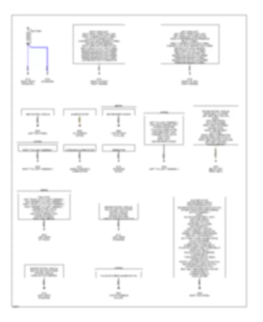
GROUND DISTRIBUTION
Ground Distribution Wiring Diagram for Volvo 940 Turbo 1995
List of elements for Ground Distribution Wiring Diagram for Volvo 940 Turbo 1995:
- Abs control module
- Battery
- Blower motor, heated rear window/ door mirrors switch, driver's door power window switch, power windows/power mirrors switch assembly, radio, glove compartment light, amplifier (radio), foglight switch, instrument cluster, ecc power unit, ecc control module, vanity mirror illumination, ambient temperature sensor, central locking relay, anti-theft alarm connector #2, cd-autochanger, lock button switch, intermittent wiper relay, tailgate intermittent wiper relay, headlight relay, bulb malfunction sensor, flasher relay, turn signal/high-low beam hazard switch, p-shift lock park position switch, heated rear window switch, power sunroof switch, seat belt reminder/ignition key warning relay, overdrive relay, cigar lighter
- Cruise control module, instrument cluster, left seat belt switch, radio, amplifier (radio), cd-autochanger, front seat backrest heater pads, front heated seat switches, front seat overheating protectors (high output), front seat control modules, left seat control module (memory)
- Engine control module, ez-k (di) ignition system control module, ez-k (di) system power amplifier, throttle position switch
- Engine control module, ez-k (di) ignition system control module, mass air flow sensor,
- Fuel pump, left trunk lid taillight assembly, left fender taillight assembly, right trunk lid taillight assembly, right fender taillight assembly, license plate lights, tailgate lock unit, high mount brake light, power antenna, roof light (sedan),
- G100 (front of left front fender)
- G101 (front of right front fender)
- G110 (left front of engine)
- G114 (left rear of engine)
- G118 (right front frame rail)
- G121 (near windshield wiper motor)
- G132 (on engine block)
- G133 (on engine)
- G200 (left kick panel)
- G203 (right kick panel)
- G207 (top of steering column)
- G300 (below left front seat)
- G404 (left taillight assembly)
- G405 (right taillight assembly)
- G407 (left rear of trunk)
- G905 (top of right "c" pillar)
- G908 (at sunroof motor)
- Generator
- Heated rear window
- Left headlight, left front park/turn lamp, left headlamp wiper motor, radio interference suppression relay (turbo), front washer motor (non-turbo), washer fluid level sensor (non-turbo), brake fluid level sensor, abs hydraulic unit (turbo), obd data link connector, engine cooling fan low-speed pressure sensor (turbo), engine cooling fan high-speed pressure sensor (turbo),
- Left taillight assembly, high mount brake light, antenna booster, tailgate wiper motor, load area roof light, license plate lights, fuel pump, roof light, heated rear window
- Right headlight, right front park/turn lamp, front washer motor (turbo), tailgate washer motor, washer fluid level sensor (turbo), heated oxygen sensor, right headlamp wiper motor, abs hydraulic unit (non-turbo), engine cooling fan low-speed pressure sensor (non-turbo), engine cooling fan high-speed pressure sensor (non-turbo), air pre-heating ptc-resistor
- Right taillight assembly
- Sedan
- Sunroof motor
- Tailgate wiper/washer switch
- Wagon
- Windshield wiper motor
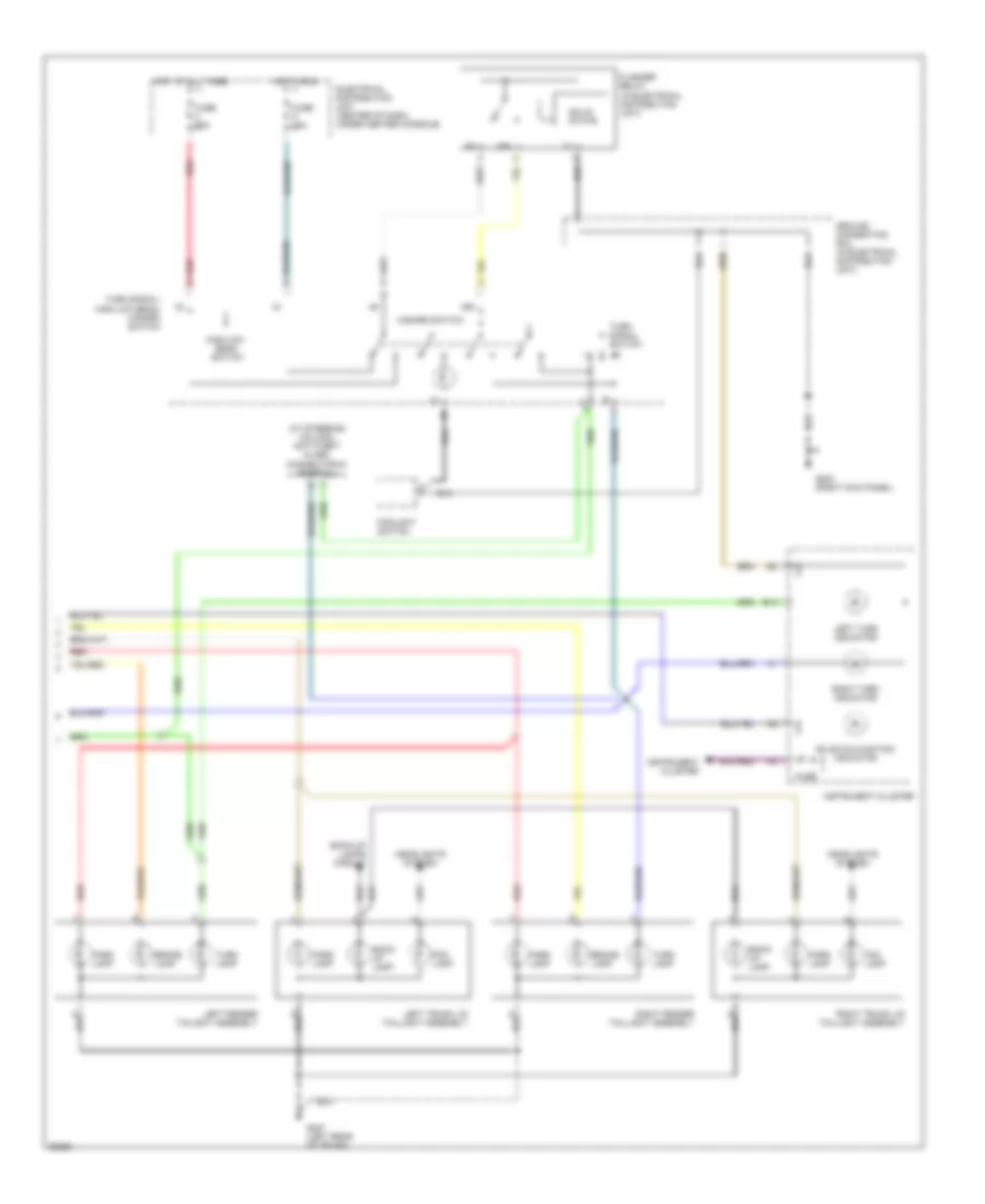
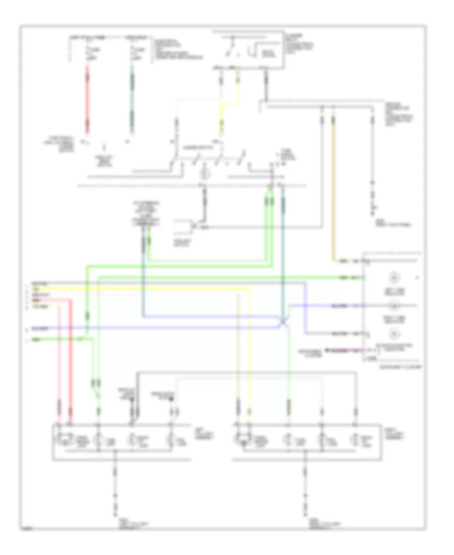
HEADLIGHTS
Headlamps/Fog Lamps Wiring Diagram for Volvo 940 Turbo 1995
List of elements for Headlamps/Fog Lamps Wiring Diagram for Volvo 940 Turbo 1995:
- (front of left front fender)
- (front of right front fender)
- (left rear of trunk)
- (left taillight assembly)
- (right kick panel)
- (right taillight assembly)
- 30 rail (electrical distribution unit)
- 56a
- 56b
- 87b
- Acc
- Battery
- Bulb malfunction indicator
- Electrical distribution unit
- Exterior lights system
- Flash
- Foglight switch
- Fuse 15a
- Fuse 25a
- G100
- G101
- G203
- G404
- G405
- G407
- Ground connection rail (electrical distribution unit)
- Head
- Headlight relay (electrical distribution unit)
- High beam indicator
- Hot at all times
- Ignition switch
- Instrument cluster
- Left headlight
- Left rear combination light
- Left rear fog light
- Light switch
- Lock
- Off
- Park
- Positive terminal
- Radio
- Rear foglights indicator
- Red
- Right headlight
- Right rear combination light
- Right rear fog light
- Run
- Sedan
- Start
- Turn signal/ high low beam switch
- Wagon
HORN
Horn Wiring Diagram for Volvo 940 Turbo 1995
List of elements for Horn Wiring Diagram for Volvo 940 Turbo 1995:
- Electrical distribution unit (center of dash, under center console)
- Fuse 25a
- Horn
- Horn switches
- Hot in acc or run
- Nca
- Slip ring
- W/ airbag only
- Windshield wash/wipe switch
- Windshield wiper intermittent relay
INSTRUMENT CLUSTER
Instrument Cluster Wiring Diagram for Volvo 940 Turbo 1995
List of elements for Instrument Cluster Wiring Diagram for Volvo 940 Turbo 1995:
- (+)
- (-)
- (2.3l turbo)
- (2.3l)
- (at steering column)
- (below left front seat)
- (front of right front fender) g101
- (twisted pair)
- (twisted wire pair)
- 87a
- A10
- A11
- A12
- A13
- A14
- Abs control module (under left side of dash)
- Abs indicator
- Acc
- Ambient temperature gauge
- Ambient temperature sensor (behind front bumper)
- Anti-lock brakes system
- Anti-theft alarm connector #2 (partial)
- B10
- B11
- B12
- B13
- B14
- Brake fluid level sensor (top of brake master cylinder reservoir)
- Brake warning indicator
- Bulb malfunction indicator
- C10
- C11
- C12
- Charging indicator
- Clock
- Cruise control module (left kick panel)
- Electrical distribution unit (center of dash, under center console)
- Electronic climate control module (center of i/p)
- Engine controls system
- Engine coolant temperature gauge
- Engine coolant temperature sensor (left side of engine)
- Engine temperature warning indicator
- Exterior lights system
- Ez-k (di) system power amplifier (left front of engine compt)
- Fuel gauge
- Fuel level sensor
- Fuel pump assembly
- Fuse
- Fuse 15a
- G100 (front of left front fender)
- G203 (right kick panel)
- G300
- Ground connector rail
- Headlights system
- Hic
- High beam indicator
- Hot at all times
- Hot in run
- Ignition coil (right rear corner of engine compt)
- Ignition switch
- Illumination lamps
- Indicator
- Instrument cluster
- Interior lights system
- Left turn indicator
- Lh-jetronic 2.4 mfi control module (right kick panel)
- Lvl
- Malfunction indicator lamp
- Off
- Oil pressure
- Oil pressure sensor (center console)
- Overdrive indicator
- Overdrive relay (in electrical distribution unit)
- Parking brake indicator
- Parking brake switch (center console)
- Prim coil
- Rear fog lamp indicator
- Red
- Rheostat
- Right turn indicator
- Run
- Seal
- Seat belt indicator
- Service indicator
- Spd in
- Speed in
- Speedometer
- Srs warning
- Start
- Starting/charging system
- Tach
- Tachometer
- Trailer indicator (not used)
- Vehicle speed/ abs sensor (rear differential)
- Warning indicator
- Warning system
- Washer fluid level indicator
- Washer fluid level sensor (left front of engine compt in reservoir)
INTERIOR LIGHTS
Courtesy Lamps Wiring Diagram for Volvo 940 Turbo 1995
List of elements for Courtesy Lamps Wiring Diagram for Volvo 940 Turbo 1995:
- (left rear of trunk)
- (right kick panel)
- Anti-theft system
- Electrical distribution unit (center of dash, behind center console)
- Fuse 15a
- G203
- G404 (left taillight assembly)
- G404 (wagon) (left taillight assembly)
- G407
- Glove compartment light
- Glove compartment switch
- Hot at all times
- Left front door open warning light
- Left front door switch
- Left rear door open warning light
- Left rear door switch
- Left vanity mirror illumination
- Load area roof light (wagon)
- Red
- Right front door open warning light
- Right front door switch
- Right rear door open warning light
- Right rear door switch
- Right vanity mirror illumination
- Roof light
- Sedan
- Solid state
- Tailgate door switch (wagon) (upper left hatch door)
- Tailgate lock unit
- Trunk light (sedan)
- Wagon
Instrument Illumination Wiring Diagram for Volvo 940 Turbo 1995
List of elements for Instrument Illumination Wiring Diagram for Volvo 940 Turbo 1995:
- (right kick panel)
- 15i
- A11
- A13
- A16
- Acc
- B12
- B13
- Battery positive terminal
- Control panel lighting
- Electrical distribution unit (center of dash, behind center console)
- Electronic climate control module
- Front ashtray lighting
- Fuse 15a
- G203
- Gear selector lighting
- Ground connection rail (electrical distribution unit)
- Head
- Headlight relay
- Heated rear window/door mirrors switch lighting
- Ignition switch
- Illumination
- Instrument cluster
- Light switch
- Manual climate control module
- Off
- Park
- Park head
- Positive terminal
- Power sunroof lighting (left i/p)
- Radio
- Rear ashtray lighting
- Red
- Rheostat
- Run
- Seat heater switch lighting (optional)
- Solid state
- Start
- Switch lighting (behind light switch)
- Voltage rail
MEMORY SYSTEMS
Memory Seat Wiring Diagram for Volvo 940 Turbo 1995
List of elements for Memory Seat Wiring Diagram for Volvo 940 Turbo 1995:
- (below left front seat) g304
- Back
- Backrest switch
- C10
- C11
- C12
- C13
- C14
- Computer data lines system (diagnostic connector)
- D10
- D11
- D12
- D13
- D14
- D15
- D16
- Down
- Electrical distribution unit (center of dash, below center console)
- Forw
- Forw-backw switch
- Front edge switch
- Fuse 25a
- Fuse 30a
- Hot at all times
- Hot in acc or run
- Left front seat backrest motor
- Left front seat forward-backward motor
- Left front seat front edge up-down motor
- Left front seat rear edge up-down motor
- Left seat control module (under left front seat)
- Left seat memory switch (on left side of seat)
- M1+
- M1-
- M2+
- M2-
- M3+
- M3-
- M4+
- M4-
- Mem
- R1+
- R1-
- R2+
- R2-
- R3+
- R3-
- R31
- R4+
- R4-
- Rear edge switch
- Red
- Vg1
- Vg2
- Vg3/4
- Vr1
- Vr2
- Vr3
- Vr4
POWER ANTENNA
Power Antenna Wiring Diagram for Volvo 940 Turbo 1995
List of elements for Power Antenna Wiring Diagram for Volvo 940 Turbo 1995:
- (left rear of trunk)
- A11
- A12
- Electrical distribution unit (center of dash, under center console)
- Fuse 15a
- G407
- Hot at all times
- Hot in acc or run
- Power antenna
- Radio
- Red
POWER DISTRIBUTION
Power Distribution Wiring Diagram (1 of 2) for Volvo 940 Turbo 1995
List of elements for Power Distribution Wiring Diagram (1 of 2) for Volvo 940 Turbo 1995:
- Abs hydraulic unit
- Battery
- Blower motor, ecc power unit, ecc control module
- Brake light switch
- Bulb malfunction indicator, left front park/turn lamp, license plate lights, instrument cluster, heated rear window/ door mirrors switch lighting, switch lighting, rheostat, power sunroof lighting, control panel lighting front ashtray lighting, ecc control module, mcc control module, radio, ambient temperature sensor
- Electrical distribution unit
- Engine control module
- Engine cooling fan relay
- Ez-k (di) system control module
- Foglight switch
- Front seat control modules, left seat control module (memory)
- Fuel injection relay (non- turbo)
- Fuel injection relay (turbo)
- Fuel pump, heated oxygen sensor (non- turbo)
- Fuse 15a
- Fuse 15a (not used)
- Fuse 25a
- Fuse 30a
- Fusible link
- Generator
- Headlight relay
- Headlights system (bulb malfunction indicator)
- Headlights system (headlight relay)
- Headlights system (turn signal/ high low-beam switch)
- Left headlight
- Left headlight, instrument cluster
- Light switch
- Non- turbo
- Non-turbo only
- Pnk
- Positive terminal
- Radio interference suppression relay
- Radio, cd-autochanger, amplifier
- Rail
- Red
- Right front park/turn lamp, bulb malfunction indicator, gear selector lighting, seat heater switch lighting, rear ashtray lighting
- Right headlight
- Starter
- To bypass relay 15i (schematic 2 of 2)
- To ignition switch (schematic 2 of 2)
- Turbo
- Turn signal/ high-low beam/ hazard switch, anti-theft alarm connector #2, central locking relay
- Vanity mirror illumination, glove compartment switch, door open warning lights, roof light, trunk light, instrument cluster, power antenna
Power Distribution Wiring Diagram (2 of 2) for Volvo 940 Turbo 1995
List of elements for Power Distribution Wiring Diagram (2 of 2) for Volvo 940 Turbo 1995:
- (right kick panel)
- 15i
- Abs control module
- Acc
- Bypass relay 15i
- Cigar lighter
- Cruise control switch, cruise control module, back-up light switch, anti-theft alarm connector #2
- Driver's door power window switch, right front power window switch
- Electrical distribution unit
- Engine control module, egr convertor, ez-k (di) system power amplifier, ez-k (di) system control module, obd data link connector
- From 30 rail (electrical distribution unit) (schematic 1 of 2)
- From positive terminal (schematic 1 of 2)
- Front heated seat switches
- Fuse 15a
- Fuse 25a
- Fuse 30a
- G203
- Ground connection rail (electrical distribution unit)
- Heated rear window switch or heated rear window/ door mirrors switch
- Heater controls, mcc a/c controls, ecc solenoids, ecc control module
- Ignition switch
- Instrument cluster, ignition coil
- Key in ignition switch
- Key-in
- Light switch
- Off
- Pnk
- Power sunroof switch, heated rear window switch, heated rear window/door mirrors switch
- Pulsed secondary air injection solenoid
- Red
- Seat belt reminder/ ignition key warning relay
- Srs sensor module
- Start
- Start inhibit switch, cruise control module, service data link connector
- Tailgate intermittent wiper relay, tailgate wiper motor, tailgate wiper/washer switch, ambient temperature sensor, radio, power door mirror switches
- Turn signal/ high-low beam/ hazard switch, seat belt reminder/ignition key warning relay, instrument cluster, brake light switch
- Windshield wiper intermittent relay, windshield wiper/washer switch, horns, headlight wiper motors, windshield wiper motor, front seat control modules, left seat control module (memory)
POWER DOOR LOCKS
Power Door Lock Wiring Diagram for Volvo 940 Turbo 1995
List of elements for Power Door Lock Wiring Diagram for Volvo 940 Turbo 1995:
- (right kick panel)
- Anti- theft system
- Central locking relay (electrical dist. unit)
- Electrical distribution unit (center of dash, under center console)
- Fuse 25a
- G203
- Ground connection rail
- Hot at all times
- Interior lights system
- Left front door lock motor
- Left rear door lock motor
- Lock button switch
- Red
- Right front door lock motor
- Right rear door lock motor
- Solid state
- Tailgate lock unit
- Tailgate locking motor
- W/ tailgate switch
- W/o tailgate switch
POWER MIRRORS
Power Mirror Wiring Diagram for Volvo 940 Turbo 1995
List of elements for Power Mirror Wiring Diagram for Volvo 940 Turbo 1995:
- Defoggers system
- Electrical distribution unit
- Fuse 15a
- G203 (right kick panel)
- Hot in run, w/ overload relay energized
- Left power door mirror
- Left power door mirror heating element
- Left power door mirror switch
- Nca
- Power windows/power mirrors switch assembly
- Right power door mirror
- Right power door mirror heating element
- Right power door mirror switch
- X-motor
- Y-motor
POWER SEATS
Heated Seats Wiring Diagram, High Output for Volvo 940 Turbo 1995
List of elements for Heated Seats Wiring Diagram, High Output for Volvo 940 Turbo 1995:
- (below left front seat)
- (not used)
- Elecrical distribution unit (center of dash, under center console)
- Fuse 25a
- G300
- Hot in run, w/ bypass relay energized
- Left front heated seat switch
- Left front seat backrest heater pad
- Left front seat overheating protector (under left front seat)
- Left front seat seat heater pad
- Off
- On indicator
- Red
- Right front heated seat switch
- Right front seat overheating protector (under right front seat)
- Right front seat seat heater pad
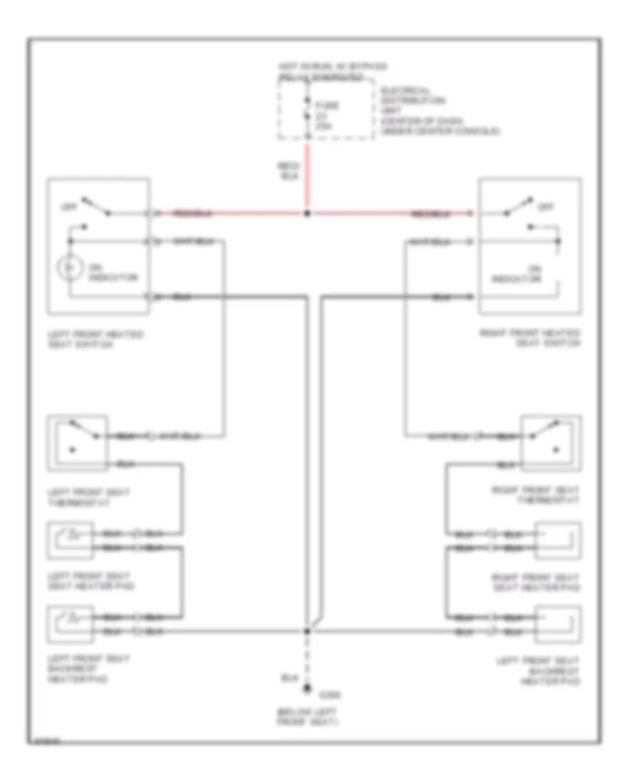
Heated Seats Wiring Diagram, Normal Output for Volvo 940 Turbo 1995
List of elements for Heated Seats Wiring Diagram, Normal Output for Volvo 940 Turbo 1995:
- (below left front seat)
- Elecrical distribution unit (center of dash, under center console)
- Fuse 25a
- G300
- Hot in run, w/ bypass relay energized
- Left front heated seat switch
- Left front seat thermostat
- Left front seat backrest heater pad
- Left front seat seat heater pad
- Off
- On indicator
- Right front heated seat switch
- Right front seat seat heater pad
- Right front seat thermostat
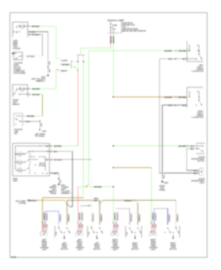
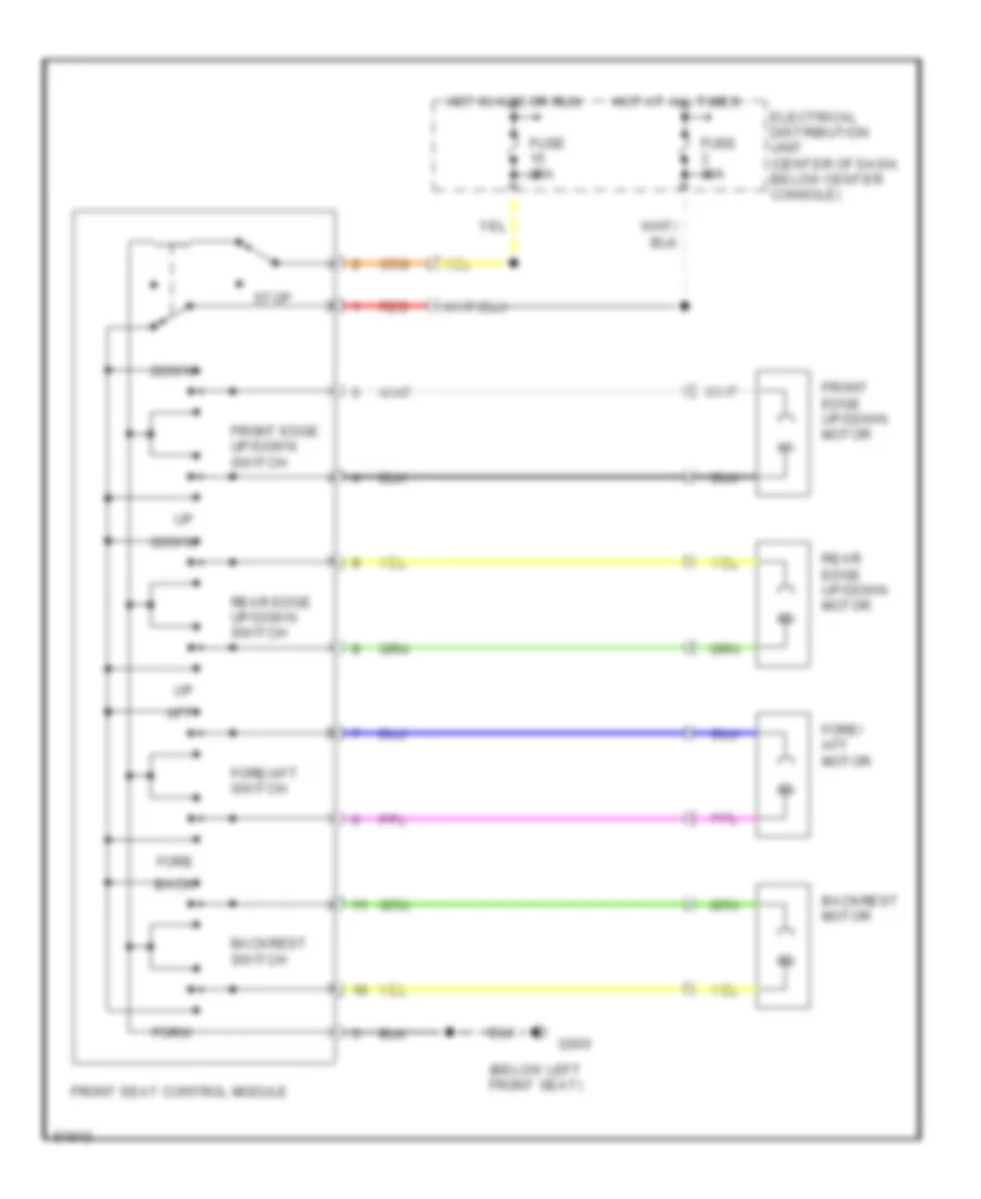
Power Seats Wiring Diagram for Volvo 940 Turbo 1995
List of elements for Power Seats Wiring Diagram for Volvo 940 Turbo 1995:
- (below left front seat)
- Aft
- Back
- Backrest motor
- Backrest switch
- Down
- Electrical distribution unit (center of dash, below center console)
- Fore
- Fore/ aft motor
- Fore/aft switch
- Forw
- Front edge up/down motor
- Front edge up/down switch
- Front seat control module
- Fuse 25a
- Fuse 30a
- G300
- Hot at all times
- Hot in acc or run
- Rear edge up/down motor
- Rear edge up/down switch
- Red
- Stop
POWER TOP/SUNROOF
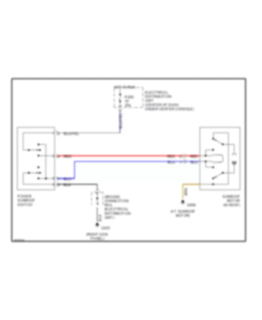
Power Top/Sunroof Wiring Diagrams for Volvo 940 Turbo 1995
List of elements for Power Top/Sunroof Wiring Diagrams for Volvo 940 Turbo 1995:
- (at sunroof motor)
- (right kick panel)
- Electrical distribution unit (center of dash, under center console)
- Fuse 30a
- G203
- G908
- Ground connection rail (electrical distribution unit)
- Hot in run
- Power sunroof switch
- Red
- Sunroof motor (in roof)
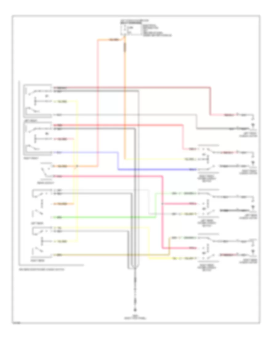
POWER WINDOWS
Power Window Wiring Diagram for Volvo 940 Turbo 1995
List of elements for Power Window Wiring Diagram for Volvo 940 Turbo 1995:
- Driver's door power window switch
- Electrical distribution unit (center of dash, under center console)
- Fuse 30a
- G203 (right kick panel)
- Hot in run w/overload relay energized
- Left front
- Left front window motor
- Left rear
- Left rear power window switch
- Left rear window motor
- Nca
- Pnk
- Rear lockout
- Red
- Right front
- Right front power window switch
- Right front window motor
- Right rear
- Right rear power window switch
- Right rear window motor
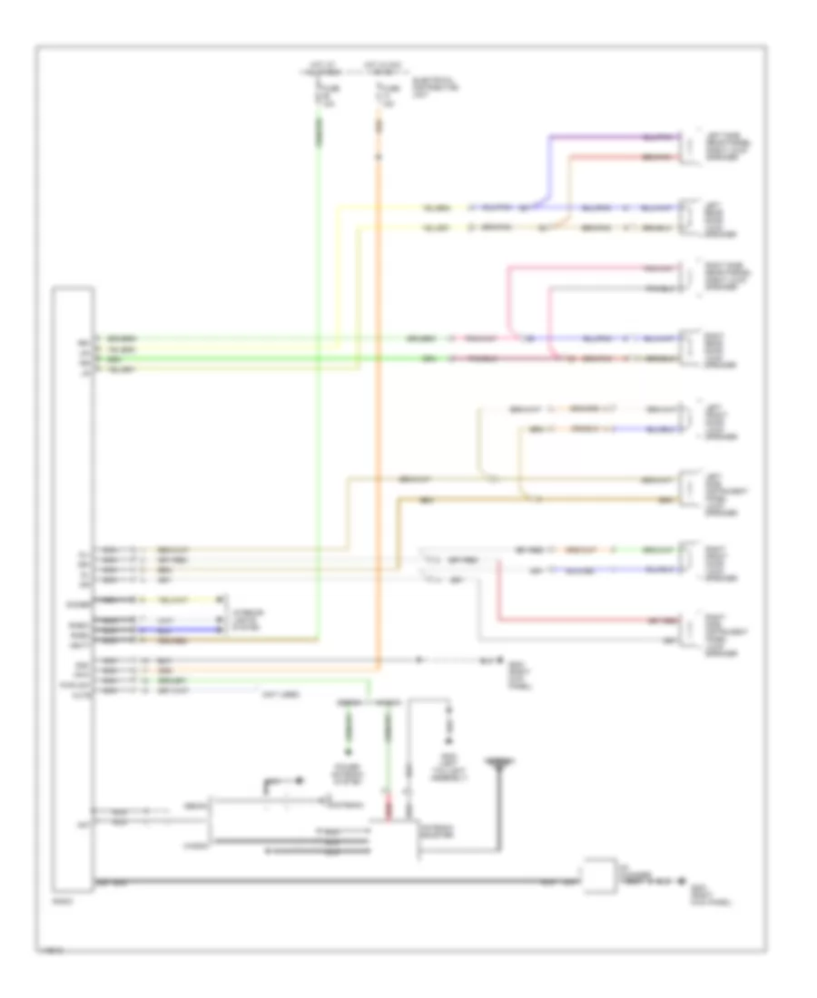
RADIO
Radio Wiring Diagrams, with Integrated Amplifier for Volvo 940 Turbo 1995
List of elements for Radio Wiring Diagrams, with Integrated Amplifier for Volvo 940 Turbo 1995:
- (below left front seat) g300
- +acc
- +ant
- +batt
- +dl
- +dr
- +lf
- +lr
- +rf
- +rheo
- +rr
- -dr
- -rheo
- -rr
- Ant
- Antenna
- Antenna booster
- Cd changer
- Dimmer
- Din
- Electrical distribution unit
- Fuse 15a
- G203 (right kick panel)
- G404 (left taillight assembly)
- Gnd
- Hot at all times
- Hot in acc or on
- Interior lights system
- Left front door loud- speaker
- Left rear door loud- speaker
- Left side instrument panel loud- speaker
- Left side rear parcel shelf loud- speaker
- Nca
- Power antenna system
- Radio
- Red
- Right front door loud- speaker
- Right rear door loud- speaker
- Right side instrument panel loud- speaker
- Right side rear parcel shelf loud- speaker
- Sedan
- Sedan only
- Wagon
- _dl
- _lf
- _lr
- _rf
Radio Wiring Diagrams, with Separated Amplifier for Volvo 940 Turbo 1995
List of elements for Radio Wiring Diagrams, with Separated Amplifier for Volvo 940 Turbo 1995:
- (behind left side of dash) amplifier
- (right kick panel)
- +batt
- Acc+
- Ant
- Antenna
- Antenna booster
- Cd changer
- Dimmer
- Din
- Dl+
- Dl-
- Dr+
- Dr-
- Electrical distribution unit
- Fuse 15a
- G203
- G203 (right kick panel)
- G404 (left taillight assembly)
- Gnd
- Hot at all times
- Hot in acc or on
- Interior lights system
- Left front door loud- speaker
- Left rear door loud- speaker
- Left side instrument panel loud- speaker
- Left side rear parcel shelf loud- speaker
- Lf+
- Lf-
- Lr+
- Lr-
- Nca
- Pwr ant
- Radio
- Red
- Rf+
- Rf-
- Rheo+
- Rheo-
- Right front door speaker
- Right rear door loud- speaker
- Right side instrument panel loud- speaker
- Right side rear parcel shelf loud- speaker
- Rr+
- Rr-
- Sedan
- Sedan only
- Wagon
Radio Wiring Diagrams, without Amplifier for Volvo 940 Turbo 1995
List of elements for Radio Wiring Diagrams, without Amplifier for Volvo 940 Turbo 1995:
- (not used)
- +batt
- Acc+
- Ant
- Antenna
- Antenna booster
- Cd changer
- Dimmer
- Din
- Dl+
- Dl-
- Dr+
- Dr-
- Electrical distribution unit
- Fuse 15a
- G203 (right kick panel)
- G404 (left taillight assembly)
- Gnd
- Hot at all times
- Hot in acc or on
- Interior lights system
- Left front door loud- speaker
- Left rear door loud- speaker
- Left side instrument panel loud- speaker
- Left side rear parcel shelf loud- speaker
- Lr+
- Lr-
- Mute
- Nca
- Power antenna system
- Pwr ant
- Radio
- Red
- Rheo+
- Rheo-
- Right front door loud- speaker
- Right rear door loud- speaker
- Right side instrument panel loud- speaker
- Right side rear parcel shelf loud- speaker
- Rr+
- Rr-
- Sedan
- Wagon
SHIFT INTERLOCKS
Shift Interlock Wiring Diagram for Volvo 940 Turbo 1995
List of elements for Shift Interlock Wiring Diagram for Volvo 940 Turbo 1995:
- Brake light switch (on brake pedal support)
- Electrical distribution unit (center of dash, under center console)
- Fuse 15a
- G203 (right kick panel)
- Ground connection rail (electrical distribution unit)
- Hot in run
- P-shift lock park position switch
- P-shift lock solenoid (base of shifter)
- Park
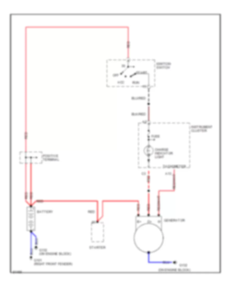
STARTING/CHARGING
Charging Wiring Diagram for Volvo 940 Turbo 1995
List of elements for Charging Wiring Diagram for Volvo 940 Turbo 1995:
- (on engine block)
- A13
- Acc
- Battery
- Charge indicator light
- Fuse
- G101 (right front fender)
- G132
- G132 (on engine block)
- Generator
- Ignition switch
- Instrument cluster
- Off
- Positive terminal
- Red
- Run
- Start
- Starter
- Tachometer
Starting Wiring Diagram for Volvo 940 Turbo 1995
List of elements for Starting Wiring Diagram for Volvo 940 Turbo 1995:
- A/t
- Acc
- Battery
- Data link connector (left side of engine compt)
- G101 (right front fender)
- G132 (on engine block)
- Generator
- Ignition switch
- Jumper
- M/t
- Off
- P or n
- Pnk
- Positive terminal
- Red
- Service pnk
- Start
- Start inhibit switch (center console, at base of shift lever)
- Starter
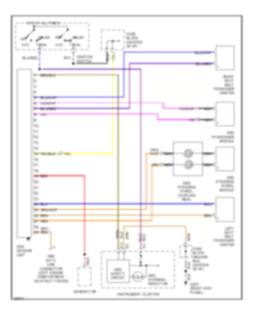
SUPPLEMENTAL RESTRAINTS
Supplemental Restraint Wiring Diagram for Volvo 940 Turbo 1995
List of elements for Supplemental Restraint Wiring Diagram for Volvo 940 Turbo 1995:
- A11
- Acc
- Fuse block (center of i/p)
- Fuse block ground rail (center of i/p)
- G203 (right kick panel)
- Generator
- Hot at all times
- Ignition switch
- Instrument cluster
- Left seat belt tensioner igniter
- Nca
- Obd data link connector (left engine compartment on strut tower)
- Off
- Red
- Right seat belt tensioner igniter
- Run
- Srs passenger module
- Srs safety circuit
- Srs sensor unit
- Srs steering wheel coupling reel
- Srs steering wheel module
- Srs warning indicator
- Start
TRANSMISSION
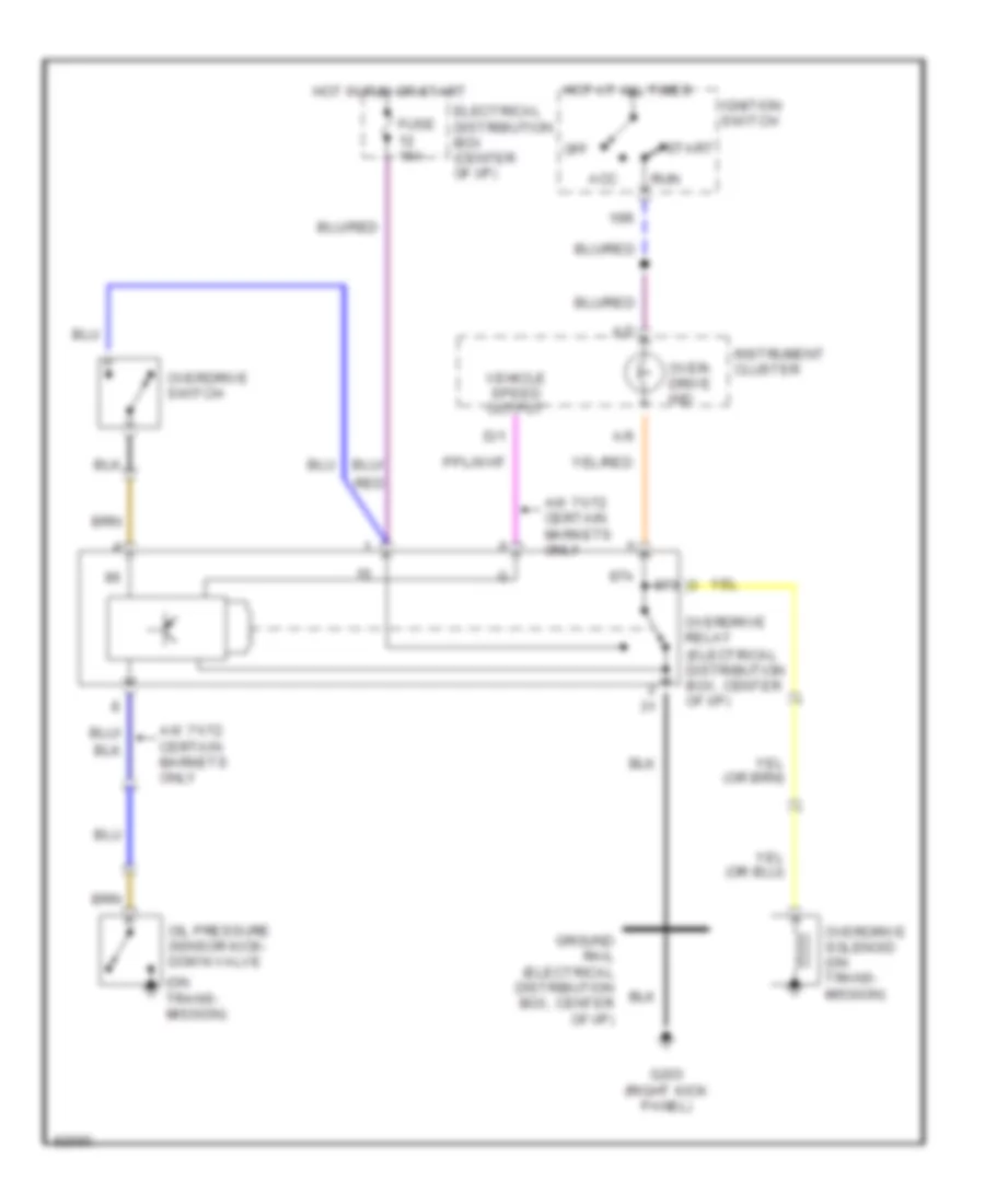
Overdrive Wiring Diagram for Volvo 940 Turbo 1995
List of elements for Overdrive Wiring Diagram for Volvo 940 Turbo 1995:
- (on trans- mission)
- 15r
- 87a
- A/2
- A/6
- Acc
- Aw 71/72 certain markets only
- D/1
- Electrical distribution box (center of i/p)
- Fuse 15a
- G203 (right kick panel)
- Ground rail (electrical distribution box, center of i/p)
- Hot at all times
- Hot in run or start
- Ignition switch
- Instrument cluster
- Off
- Oil pressure sensor kick- down valve
- Over- drive ind
- Overdrive relay (electrical distribution box, center of i/p)
- Overdrive solenoid (on trans- mission)
- Overdrive switch
- Red
- Run
- Start
- Vehicle speed output
WARNING SYSTEMS
Warning System Wiring Diagrams for Volvo 940 Turbo 1995
List of elements for Warning System Wiring Diagrams for Volvo 940 Turbo 1995:
- (below left front seat)
- Driver's door switch
- Electrical distribution unit (center of dash, under center console)
- Fuse 15a
- G203 (right kick panel)
- G300
- Gf/l
- Gf2
- Hot at all times
- Hot in run
- Ignition switch
- Instrument cluster
- Key-in ignition switch
- Left seat belt switch
- Seat belt indicator
- Seat belt reminder/ ignition key warning relay (electrical distribution unit)
WIPER/WASHER
Front Wiper/Washer Wiring Diagram for Volvo 940 Turbo 1995
List of elements for Front Wiper/Washer Wiring Diagram for Volvo 940 Turbo 1995:
- (front of right front fender)
- (right kick panel)
- 31b
- 53a
- 53b
- Electrical distribution unit (center of dash, under center console)
- Front washer motor
- Fuse 25a
- G101
- G121 (near windshield wiper motor)
- G203
- Ground connection rail (electrical distribution unit)
- Horns system
- Hot in acc or run
- Int
- Intermittent wiper relay
- Off
- Solid state
- Washer switch
- Windshield wiper motor
- Windshield wiper/washer switch
- Wiper switch
Headlamp Wiper/Washer Wiring Diagram for Volvo 940 Turbo 1995
List of elements for Headlamp Wiper/Washer Wiring Diagram for Volvo 940 Turbo 1995:
- (front of left front fender)
- (front of right front fender)
- (right kick panel)
- 53a
- Electrical distribution unit (center of dash, under center console)
- Front washer motor
- Fuse 25a
- G100
- G101
- G203
- Ground connection rail (electrical distribution unit)
- Hot in acc or run
- Intermittent wiper relay
- Left headlamp wiper motor
- Red
- Right headlamp wiper motor
- Solid state
- Washer switch
- Windshield wiper/washer switch
Rear Wiper/Washer Wiring Diagram for Volvo 940 Turbo 1995
List of elements for Rear Wiper/Washer Wiring Diagram for Volvo 940 Turbo 1995:
- (left taillight assembly)
- (right kick panel)
- 31b
- 53a
- Electrical distribution unit (center of dash, under center console)
- Fuse 25a
- G101 (front of right front fender)
- G203
- G300 (top of steering column)
- G404
- Ground connection rail (electrical distribution unit)
- Hot in acc or run
- Int
- Nca
- Red
- Solid state
- Tailgate intermittent wiper relay (electrical distribution unit)
- Tailgate washer motor
- Tailgate wiper motor
- Tailgate wiper/washer switch
- Washer switch
- Wipe
- Wiper/washer switch

 Čeština
 Dansk
Dansk Deutsch
 Ελληνικά
 English
 Español
 Suomi
Suomi Français
 Français
 עברית
עברית Hrvatski
 Magyar
 Italiano
 日本語
日本語 한국어
한국어 Nederlands
 Polski
 Português
 Português
 Română
 Русский
 Slovenčina
 Slovenščina
 Svenska
 Türkçe
 中文 (中国)