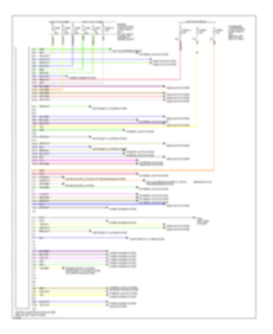
AIR CONDITIONING
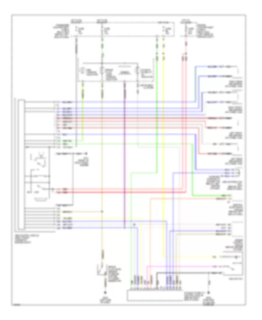
Automatic A/C Wiring Diagram (1 of 2) for Volvo S40 2000
 https://portal-diagnostov.com/license.html
Automotive Electricians Portal FZCO
Automotive Electricians Portal FZCO
https://portal-diagnostov.com/license.html
https://portal-diagnostov.com/license.html
Automotive Electricians Portal FZCO
Automotive Electricians Portal FZCO
List of elements for Automatic A/C Wiring Diagram (1 of 2) for Volvo S40 2000:
- (left side of dash)
- A/c compressor control module (behind left center of dash)
- A/c pressure sensor (in left front corner of eng compartment)
- Blower motor (behind right side of dash, on hvac housing)
- Computer data lines
- Defogger system
- Distribution rail
- Distribution rail (behind left side of dash)
- Ecc blower motor speed regulator (under right side of dash, in hvac housing)
- Ecc control module (integral with a/c controls, in center of dash)
- Ecc engine coolant temperature sensor (behind center of dash)
- Ecc evaporator & ecc outside temperature sensors (behind right side of dash, on hvac housing)
- Ecc evaporator temperature sensor (behind right side of dash, on hvac housing)
- Ecc sun sensor (on right side of dash, on corner of speaker grille)
- Floor & defroster shutter motor (ecc) (behind center of dash, on end of hvac housing)
- Fuse 15a
- Fuse 25a
- G202
- G202 (behind left side of dash)
- G202 (behind right side of dash)
- Heating system relay
- Hot at all times
- Hot in run
- Illum
- Instrument cluster sys
- J14 nca
- Maximum speed blower motor relay (ecc) (behind right side of dash, above kick panel)
- Passenger compartment fuse & relay box (behind left end of dash)
- Pnk
- Recirculation shutter motor (behind right side of dash, on end of hvac housing)
- Red
- Starting/ charging system
- Temperature shutter motor (behind center of dash, on end of hvac housing)
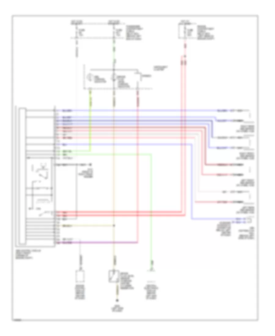
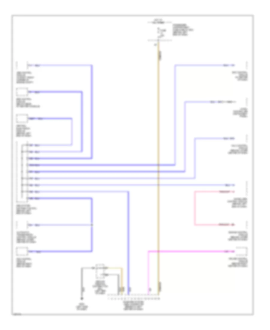
Automatic A/C Wiring Diagram (2 of 2) for Volvo S40 2000
List of elements for Automatic A/C Wiring Diagram (2 of 2) for Volvo S40 2000:
- (behind left side of dash) distribution rail
- A/c comp relay (in eng compt fuse & relay box)
- A/c condenser fan (in front of eng compt, beside left headlight)
- A/c control module (integral with a/c controls, in center of dash)
- A11
- A13
- A24
- Accessory relay (in pass compt fuse & relay box)
- Air conditioning (a/c) compressor
- Blower motor fan control
- Central electric module (cem) (behind left end of dash)
- Defogger system
- Distribution rail (behind left side of dash)
- Electronic instruments
- Engine compartment fuse & relay box (in left rear corner of engine compartment)
- Engine control module (ecm) (behind lower center of dash)
- Engine coolant temperature (ect) sensor (on front of engine)
- Engine cooling fan motor (in front of eng compt)
- Engine cooling fan relay (speed 1) (in engine compt fuse & relay box)
- Engine cooling fan relay (speed 2) (in engine compt fuse & relay box)
- Fuse 15a
- Fuse 30a
- G100 (front of left front fender)
- G101 (front of right front fender)
- G13
- G202 (behind left side of dash)
- Hot at all times
- Hot in run
- Illum
- Instrument panel
- Nca
- Passenger compartment fuse & relay box (behind left end of dash)
- Red
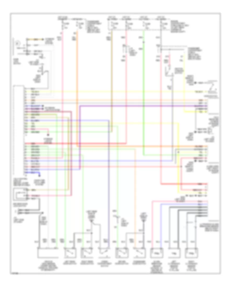
ANTI-LOCK BRAKES
Anti-lock Brake Wiring Diagrams, with Dynamic Stability Control for Volvo S40 2000
List of elements for Anti-lock Brake Wiring Diagrams, with Dynamic Stability Control for Volvo S40 2000:
- A17
- Abs control module (right front corner of engine compt)
- Abs warning indicator
- B14
- B16
- B22
- Brake fluid level sensor (in brake master cylinder reservoir)
- Brake fluid level warning indicator
- Central electronic module (behind left end of dash)
- Dsa switch
- Dynamic stability control module (behind right end of dash)
- Dynamic stability on indicator
- E11
- Engine compartment fuse & relay box (left rear of engine compt)
- Engine control module (behind center of dash)
- Fuse a12 50a
- Fuse b11 10a
- Fuse b4 10a
- Fuse b6 15a
- G101 (front of right front fender)
- G202 (left side of dash)
- G302 (forward of center console)
- Hot at all times
- Hot in on
- Hot in on or start
- I14
- Instrument cluster
- Left front abs sensor (on wheel hub)
- Left rear abs sensor (on wheel hub)
- Nca
- Obd distribution rail (behind left side of dash)
- On-board diagnostic connector (below left center of dash)
- Passenger compartment fuse & relay box (behind left end of dash)
- Red
- Right front abs sensor (on wheel hub)
- Right rear abs sensor (on wheel hub)
- Speedo
Anti-lock Brake Wiring Diagrams, without Dynamic Stability Control for Volvo S40 2000
List of elements for Anti-lock Brake Wiring Diagrams, without Dynamic Stability Control for Volvo S40 2000:
- A17
- Abs control module (right front corner of engine compt)
- Abs warning indicator
- B14
- B16
- Brake fluid level sensor (in brake master cylinder reservoir)
- Brake fluid level warning indicator
- Central electronic module (behind left end of dash)
- E11
- Engine compartment fuse & relay box (left rear of engine compt)
- Engine control module (behind center of dash)
- Fuse a12 50a
- Fuse b11 10a
- Fuse b4 10a
- G101 (front of right front fender)
- G202 (left side of dash)
- Hot at all times
- Hot in on or start
- Instrument cluster
- Left front abs sensor (on wheel hub)
- Left rear abs sensor (on wheel hub)
- Nca
- Obd distribution rail (behind left side of dash)
- On-board diagnostic connector (below left center of dash)
- Passenger compartment fuse & relay box (behind left end of dash)
- Red
- Right front abs sensor (on wheel hub)
- Right rear abs sensor (on wheel hub)
- Speedo
ANTI-THEFT
Anti-theft Wiring Diagram for Volvo S40 2000
List of elements for Anti-theft Wiring Diagram for Volvo S40 2000:
- (left rear side of cargo compt) g404
- (left side of dash) g202
- (right rear of cargo compt) g405
- Alarm horn (left front of engine compt)
- C10
- Cargo compartment switch
- Computer data lines system
- Door lock switch
- Driver door switch
- Driver's door lock switch
- E10
- Engine compartment fuse & relay box (in left rear corner of engine compt)
- Exterior lights system
- F10
- Fuse 10a
- Fuse 15a
- Fuse 20a
- G15
- G16
- G202 (left side of dash)
- G405 (right rear of cargo compt)
- Glass breakage sensor (on roof, at center of windshield)
- Hood switch
- Hot at all times
- Hot in on
- Hot in on or start
- Ignition warning switch
- Interior lights system
- J/c (left side of dash)
- Left rear door switch
- Left ultrasonic sensor (top of "a" pillar)
- Nca
- Passenger compartment fuse & relay box (behind left end of dash)
- Passenger door switch
- Pnk
- Red
- Right rear door switch
- Right ultrasonic sensor (top of "a" pillar)
- Ultrasonic glass breakage sensor (below right side of dash)
- Vehicle lean sensor (under center console, forward of gearshift)
- Vgla control module (behind lower center of dash)
- Vgla receiver (in rear of engine compt)
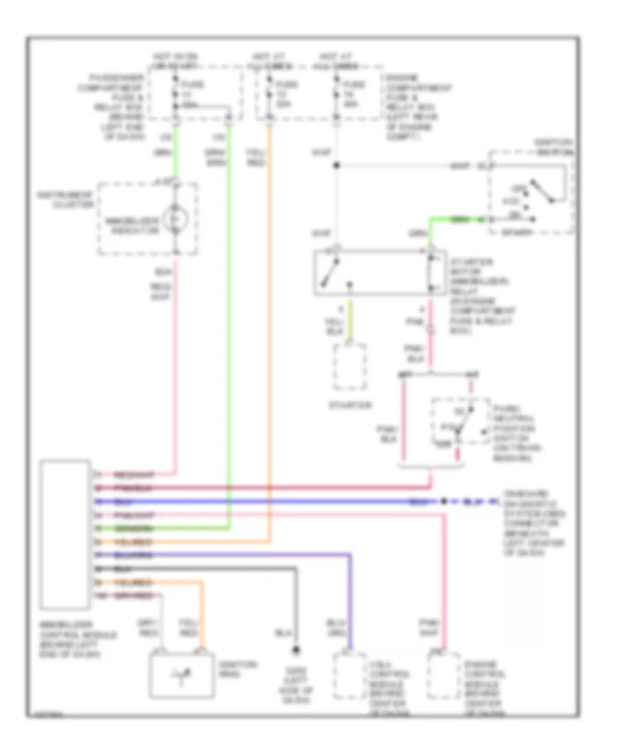
Immobilizer Wiring Diagram for Volvo S40 2000
List of elements for Immobilizer Wiring Diagram for Volvo S40 2000:
- 50s
- A/t
- A17
- Acc
- B24
- Engine compartment fuse & relay box (left rear of engine compt)
- Engine control module (behind center of dash)
- Fuse 10a
- Fuse 20a
- Fuse 40a
- G202 (left side of dash)
- Hot at all times
- Hot in on or start
- I15
- Ignition ring
- Ignition switch
- Immobilizer control module (behind left end of dash)
- Immobilizer indicator
- Instrument cluster
- M/t
- Off
- On-board diagnostic system (obd) connector (beneath left center of dash)
- P/n
- Park/ neutral position switch (on trans- mission)
- Passenger compartment fuse & relay box (behind left end of dash)
- Pnk
- Start
- Starter
- Starter motor (immobilizer) relay (in engine compartment fuse & relay box)
- Vgla control module (behind center of dash)
BODY COMPUTER
Body Computer Wiring Diagrams for Volvo S40 2000
List of elements for Body Computer Wiring Diagrams for Volvo S40 2000:
- (brake switch)
- Anti-lock brake system
- Anti-lock brake system (w/ dstc), transmissions system
- C12
- Central electronic module (cem) (behind left end of dash)
- Computer data lines system
- Cruise control system
- Cruise control system or transmissions system
- Cruise control system, instrument cluster system, air conditioning system
- E13
- Engine compartment fuse & relay box (in left rear corner of engine compt)
- Exterior lights or headlights system
- Exterior lights system
- F10
- F11
- F12
- F13
- F14
- F15
- F16
- Fuse 10a
- Fuse 14 20a
- Fuse 15a
- Fuse 18 10a
- Fuse 20a
- Fuse 4 10a
- Fuse 6 15a
- G202 (left side of dash)
- Headlights system
- Hot at all times
- Hot in acc or on
- I22
- Instrument cluster system
- Interior lights system
- Interior lights system, air conditioning system
- N/a
- P10
- P11
- P12
- P13
- P14
- P15
- P16
- P17
- P18
- Passenger compartment fuse & relay box (behind left end of dash)
- Pnk
- Sound system
- Wiper/washer system
COMPUTER DATA LINES
Computer Data Lines for Volvo S40 2000
List of elements for Computer Data Lines for Volvo S40 2000:
- (left side of dash)
- Abs control module (in right front corner of engine compt)
- Automatic transmission control module (behind lower center of dash)
- B19
- B2/7
- Central electronic module (behind left end of dash)
- Cruise control module (behind right center of dash)
- Dsa control module (behind right end of dash)
- E10
- Ecc control module (in center of dash)
- Engine control module (behind lower center of dash)
- Fuse 15a
- G202
- Ground terminal distribution rail (left end of dash)
- Hot at all times
- Immobilizer control module (behind left end of dash)
- Micro- controller (instrument panel)
- Nca
- Obd system distribution rail (behind left end of dash)
- On-board system (obd) connector (beneath left center of dash)
- Passenger compartment fuse & relay box (behind left end of dash)
- Srs control module (below rear of center console)
- Vgla control module (behind lower center of dash)
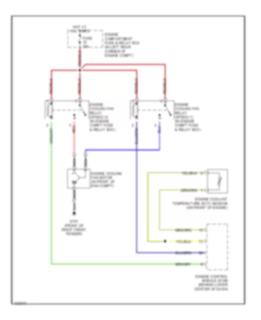
COOLING FAN
Cooling Fan Wiring Diagram for Volvo S40 2000
List of elements for Cooling Fan Wiring Diagram for Volvo S40 2000:
- Engine compartment fuse & relay box (in left rear corner of engine compt)
- Engine control module (ecm) (behind lower center of dash)
- Engine coolant temperature (ect) sensor (on front of engine)
- Engine cooling fan motor (in front of eng compt)
- Engine cooling fan relay (speed 1) (in engine compt fuse & relay box)
- Engine cooling fan relay (speed 2) (in engine compt fuse & relay box)
- Fuse 30a
- G101 (front of right front fender)
- Hot at all times
- Nca
- Red
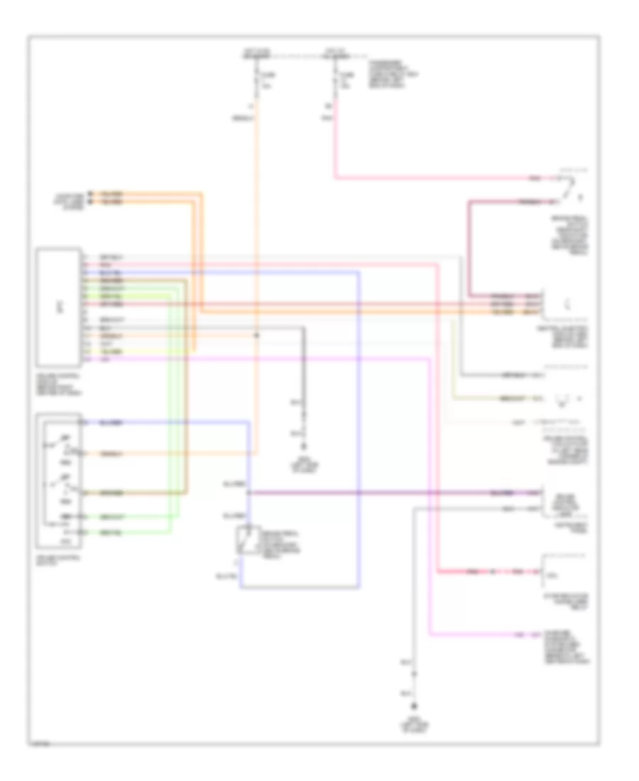
CRUISE CONTROL
Cruise Control Wiring Diagram for Volvo S40 2000
List of elements for Cruise Control Wiring Diagram for Volvo S40 2000:
- A13
- A18
- Acc
- B1/3
- B1/5
- B2/16
- Brake pedal switch (gear shift indicator) (on bracket, above brake pedal)
- Brake pedal switch (on bracket, above brake pedal)
- Central electric module (cem) (behind left end of dash)
- Coil
- Computer data lines system
- Cruise control indicator lamp
- Cruise control module (behind right center of dash)
- Cruise control switch
- Cruise control vacuum pump (in left rear corner of engine compt)
- Dec
- Fuse 10a
- Fuse 15a
- G202 (left side of dash)
- Hot at all times
- Hot in on or start
- Instrument panel
- Off
- On-board diagnostic system (obd) connector (beneath left center of dash)
- Passenger compartment fuse & relay box (behind left end of dash)
- Pnk
- Res
- Starter motor (immobilizer) relay
DEFOGGERS
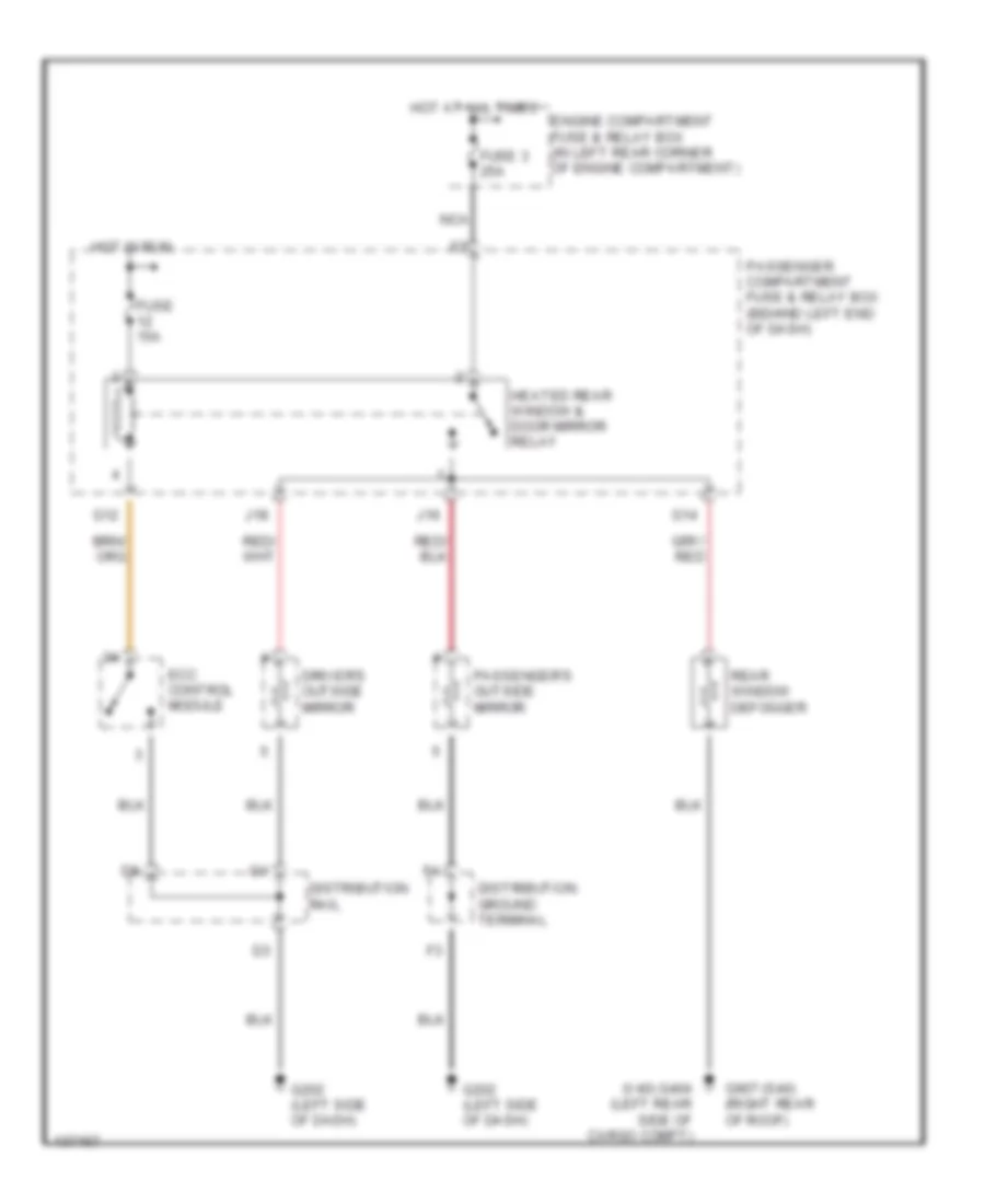
Defogger Wiring Diagram for Volvo S40 2000
List of elements for Defogger Wiring Diagram for Volvo S40 2000:
- (v40) g404 (left rear side of cargo compt)
- Distribution ground terminal
- Distribution rail
- Driver's outside mirror
- Ecc control module
- Engine compartment fuse & relay box (in left rear corner of engine compartment)
- Fuse 15a
- Fuse 3 25a
- G12
- G14
- G202 (left side of dash)
- G907 (s40) (right rear of roof)
- Heated rear window & door mirror relay
- Hot at all times
- Hot in run
- J16
- J18
- Nca
- Passenger compartment fuse & relay box (behind left end of dash)
- Passenger's outside mirror
- Rear window defogger
ENGINE PERFORMANCE
1.9L
1.9L Turbo, Engine Performance Wiring Diagrams (1 of 3) for Volvo S40 2000
List of elements for 1.9L Turbo, Engine Performance Wiring Diagrams (1 of 3) for Volvo S40 2000:
- (in left front corner of engine compt) canister purge (cp) valve
- (on left side of engine compt) mass airflow (maf) sensor
- (on left side of engine compt, near air cleaner) turbocharger (tc) control valve
- (on top of cylinder head) ignition coil (1 & 4 cyl)
- (on top of cylinder head) ignition coil (2 & 3 cyl)
- + nca
- - nca
- A17
- Abs system
- B10
- B23
- Cooling fans system
- Engine control module (ecm) (behind lower center of dash)
- Engine speed (rpm) sensor (on lower front of engine)
- Exhaust warning lamp
- G134 (top of engine)
- G302 (below center console)
- Instrument cluster
- Leak diagnostic pump (ldp) (under left rear of vehicle)
- Micro-controller
- Nca
- Noise filter
- Pnk
- Red
- Tachometer
- Transmissions system
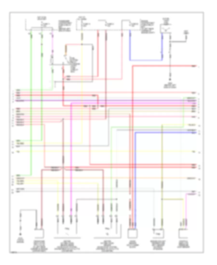
1.9L Turbo, Engine Performance Wiring Diagrams (2 of 3) for Volvo S40 2000
List of elements for 1.9L Turbo, Engine Performance Wiring Diagrams (2 of 3) for Volvo S40 2000:
- (in fuel tank) fuel pump
- (not used)
- Crankcase ventilation (ptc) valve (in left rear corner of engine compartment)
- Engine compartment fuse & relay box (in left rear corner of engine compt)
- Engine coolant temperature (ect) sensor (on front of engine)
- Fuel system relay (in engine compt fuse & relay box)
- Fuse 11 10a
- Fuse 13 20a
- Fuse 20 15a
- Fuse 21 10a
- G134 (top of engine)
- G202 (behind left side of dash)
- Heated oxygen (ho2s) sensor (on exhaust system, upstream of catalytic converter)
- Heated oxygen (ho2s) sensor (rear) (on exhaust system, downstream of catalytic converter)
- Hot at all times
- Hot in on or start
- I13
- I14
- Knock sensor (on cylinder block)
- Manifold absolute pressure (map) sensor
- Nca
- Passenger compartment fuse & relay box (behind left end of dash)
- Pnk
- Red
1.9L Turbo, Engine Performance Wiring Diagrams (3 of 3) for Volvo S40 2000
List of elements for 1.9L Turbo, Engine Performance Wiring Diagrams (3 of 3) for Volvo S40 2000:
- (behind left end of dash) immobilizer control module
- (in right front corner of engine compartment) abs control module
- (on cylinder head) cvvt valve
- (on left side of cylinder head) idle air control (iac) valve
- A/c pressure sensor (in left front corner of engine compartment)
- A/c system
- Abs system
- Altitude sensor (on center of firewall)
- Camshaft position sensor (on cylinder head)
- Engine control module (ecm) (behind lower center of dash)
- Fuel injectors
- Intake air temperature (iat) sensor (on engine air intake tract)
- Nca
- Pnk
- Red
- Throttle position sensor (on throttle body)
- Transmissions system
EXTERIOR LIGHTS
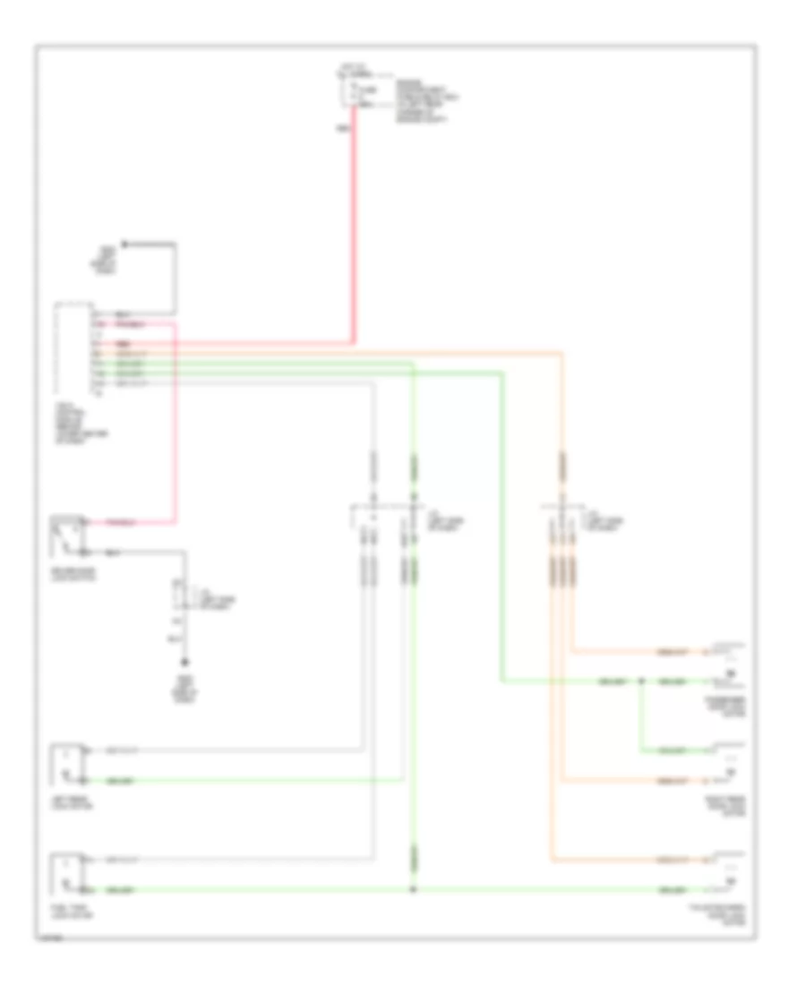
Back-up Lamps Wiring Diagram for Volvo S40 2000
List of elements for Back-up Lamps Wiring Diagram for Volvo S40 2000:
- (left rear side of trunk)
- (left side of dash)
- (right rear side of trunk)
- A/t
- B1/1
- B1/8
- B1/9
- B2/1
- Back-up lamp switch (on transmission)
- C12
- Central electric module (cem) (behind left end of dash)
- Fuse 10a
- Fuse 15a
- G202
- G404
- G405
- Hot in run
- Hot in run or start
- I22
- Left & right back-up lamps
- Left back-up lamp
- M/t
- Passenger compartment fuse & relay box (behind left end of dash)
- Right back-up lamp
- S40
- V40
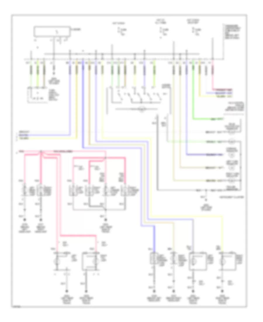
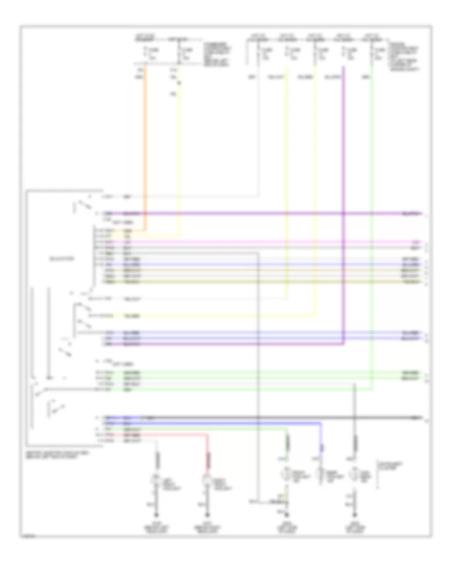
Exterior Lamps Wiring Diagram (1 of 2) for Volvo S40 2000
List of elements for Exterior Lamps Wiring Diagram (1 of 2) for Volvo S40 2000:
- (left side of dash) g202
- (on bracket above brake pedal) stoplight switch
- 15/1
- Accessory cable harness (in trunk)
- B1/1
- B1/10
- B1/2
- B1/3
- B1/6
- B2/1
- B2/5
- C12
- Central electric module (cem) (behind left end of dash)
- Drl
- Engne compartment fuse & relay box (left rear corner of engine compt)
- F11
- Fuse 10a
- Fuse 15a
- G10
- G106 (behind left headlamp)
- G107 (behind right headlamp)
- G107 (behind right headllamp)
- G404 (left rear side of trunk)
- G405 (right rear side of trunk)
- G6 g6
- Head
- High- mount stop lamp
- Hot at all times
- Hot in run
- Hot in run or start
- I22
- Illumination
- Left front lamp module
- Left front park lamp
- Left rear park lamp
- Left stop lamp
- Light switch
- Off
- P16
- P17
- P18
- Park
- Park lamp
- Passenger compartment fuse & relay box (behind left end of dash)
- Pnk
- Right front lamp module
- Right front park lamp
- Right rear park lamp
- Right stop lamp
- S40
- S40 only
- Shift interlock system
- Transmissions system
- Turn lamp
- V40
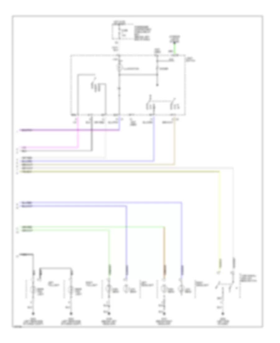
Exterior Lamps Wiring Diagram (2 of 2) for Volvo S40 2000
List of elements for Exterior Lamps Wiring Diagram (2 of 2) for Volvo S40 2000:
- A12
- A13
- A15
- A17
- A22
- A26
- B18
- Bulb malfunction indicator
- C12
- C14
- C15
- C16
- C17
- E20
- Flasher
- Fuse 10a
- Fuse 15a
- G106 (behind left headlamp)
- G107 (behind right headlamp)
- G17
- G18
- G19
- G202 (left side of dash)
- G404 (left rear side of trunk)
- G405 (right rear side of trunk)
- Hazard switch
- Hot at all times
- Hot in run
- Hot in run or start
- I19
- I20
- I21
- Instrument cluster
- Left front fender turn lamp
- Left license plate lamp
- Left rear park lamp
- Left rear turn lamp
- Left tail lamp
- Left turn indicator
- Passenger compartment fuse & relay box (behind left end of dash)
- Pnk
- Right front fender turn lamp
- Right license plate lamp
- Right rear park lamp
- Right rear turn lamp
- Right tail lamp
- Right turn indicator
- S40 only
- Trailer indicator
- Turn signal/ high-low beam switch
- V40 only
- Vgla control module (behind lower center of dash)
- Warning indicator
GROUND DISTRIBUTION
Ground Distribution Wiring Diagram for Volvo S40 2000
List of elements for Ground Distribution Wiring Diagram for Volvo S40 2000:
- A/c compressor
- A/c compressor control module
- A/c control module (manual a/c)
- A/t gear position lights
- Abs control module
- Accessory relay
- Alarm horn
- Ashtray lighting
- Automatic transmission
- Automatic transmission switch (econ/sport)
- Automatic transmission switch (winter)
- Bass speaker
- Battery
- Blower controls
- Brake fluid level sensor
- Camshaft position (cmp) sensor
- Capacitor
- Cargo compartment light
- Central electronic module (cem)
- Cigarette lighter
- Condenser fan
- Connector (acc)
- Crankcase ventilation
- Cruise control ecu
- Door lock switch
- Driver's door lock switch
- Driver's door switch
- Driver's mirror switch
- Driver's outside door mirror
- Driver's power seat
- Driver's power window switch
- Driver's seat heater
- Driver's seat heater switch
- Dsa control
- Ecc control module blower switch (manual a/c)
- Ecc fan motor speed regulator
- Engine control module
- Engine cooling fan
- Front fog lamps indicator light
- G106 (behind left headlamp)
- G107 (behind right headlamp)
- G111 (near battery)
- G123 (right side of firewall)
- G134 (top of engine)
- G202 (left side of dash)
- G206 (center of dash)
- G302 (below center console)
- G404 (left rear side of cargo compt)
- G405 (right rear side of cargo compt)
- G907 (right rear of roof)
- Glove compartment light
- Hazard switch
- Headlamp alignment control module
- Heated oxygen sensor (ho2s) (screen)
- Heater controls
- Heating system relay
- Hi speed blower fan motor relay (ecc)
- High beam switch
- High level brake lamp (v40)
- High level center brake light (s40)
- Hood catch switch
- Horn switches
- Ignition warning control module
- Immobilzer control module
- Instrument panel
- Kick-down switch
- Left fender turn signal lamp
- Left front fog lamps
- Left front parking lamp
- Left headlamp
- Left headlamp height adjustment motor
- Left headlamp wiper motor
- Left rear combination lamps
- Left rear door switch
- Left turn signal lamp & parking lamp
- License plate lamps
- Module automatic transmission control module
- Park/neutral position switch
- Passenger compartment fuse box
- Passenger's airbag switch
- Passenger's door switch
- Passenger's mirror switch
- Passenger's outside door mirror
- Passenger's power seat
- Passenger's power window switch
- Passenger's seat heater
- Passenger's seat heater switch
- Power antenna (s40)
- Power sunroof switch
- Power window auto-down relay
- Power window relay
- Radio
- Reading lights
- Rear bulb failure sensor
- Rear door lock switch
- Rear power window switches
- Rear window defogger (s40)
- Rear window defogger (v40)
- Rear window washer motor
- Rear wiper motor (v40)
- Right fender turn signal lamp
- Right front fog lamps
- Right front parking lamp
- Right headlamp
- Right headlamp height adjustment motor
- Right headlamp wiper motor
- Right rear combination lamps (s40)
- Right rear combination lamps (v40)
- Right rear door switch
- Right turn signal lamp & parking lamp
- Shift lock solenoid
- Sun sensor led
- Vacuum pump motor
- Vgla door lock & alarm control module
- Vgla receiver
- Wide open throttle switch
- Windshield washer motor
- Windshield washer reservoir level sensor
- Windshield wiper motor
HEADLIGHTS
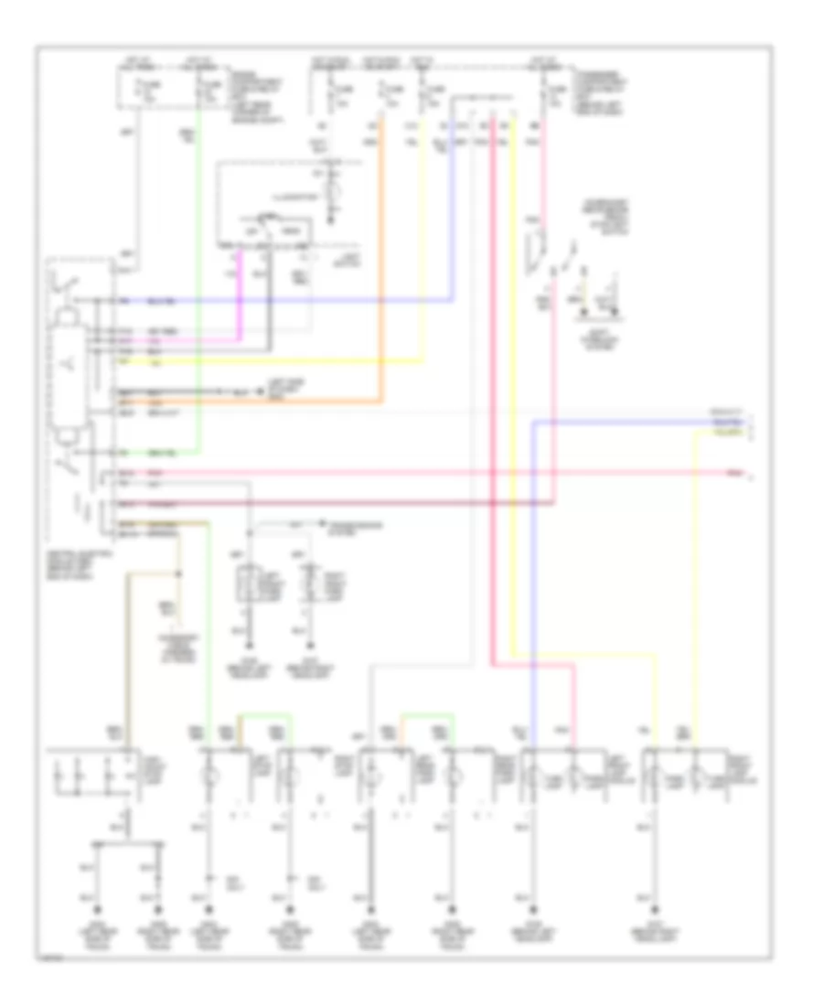
Headlamps & Fog Lamps Wiring Diagram (1 of 2) for Volvo S40 2000
List of elements for Headlamps & Fog Lamps Wiring Diagram (1 of 2) for Volvo S40 2000:
- (not used)
- A13
- B1/1
- B1/11
- B17
- B2/1
- B2/3
- B2/4
- C12
- Central electric module (cem) (behind left end of dash)
- Engine compartment fuse & relay box (in left rear corner of engine compt)
- F11
- F12
- F13
- F14
- F15
- F16
- Front foglight ind
- Fuse 10a
- Fuse 15a
- Fuse 20a
- G106 (behind left headlamp)
- G107 (behind right headlamp)
- G202 (left side of dash)
- High beam ind
- Hot at all times
- Hot in on
- Hot in on or start
- I22
- Instrument cluster
- Left front foglight
- Nca
- P10
- P12
- P13
- P16
- P17
- P18
- Passenger compartment fuse & relay box (behind left end of dash)
- Rear foglight ind
- Right front foglight
- Solid state
Headlamps & Fog Lamps Wiring Diagram (2 of 2) for Volvo S40 2000
List of elements for Headlamps & Fog Lamps Wiring Diagram (2 of 2) for Volvo S40 2000:
- (not used)
- +15/1
- 51d
- 56a
- 58/3
- Dimmer
- Drl
- Fuse 10a
- G106 (behind left headlamp)
- G107 (behind right headlamp)
- G202 (left side of dash)
- G404 (left rear side of cargo compt)
- Head
- High beam
- Hot in on or start
- Illumination
- Interior lights system
- Left headlight
- Left taillight
- Light switch
- Low beam
- Nca
- Off
- Park
- Passenger compartment fuse & relay box (behind left end of dash)
- Rear fog- light
- Right headlight
- Right taillight
- Turn signal/ high-low beam switch
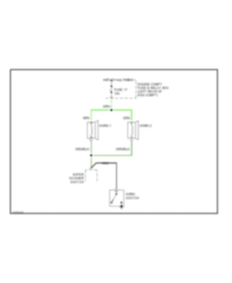
HORN
Horn Wiring Diagram for Volvo S40 2000
List of elements for Horn Wiring Diagram for Volvo S40 2000:
- Engine compt fuse & relay box (left rear of eng compt)
- Fuse 17 15a
- Horn 1
- Horn 2
- Horn switch
- Hot at all times
- Nca
- Wiper washer switch
INSTRUMENT CLUSTER
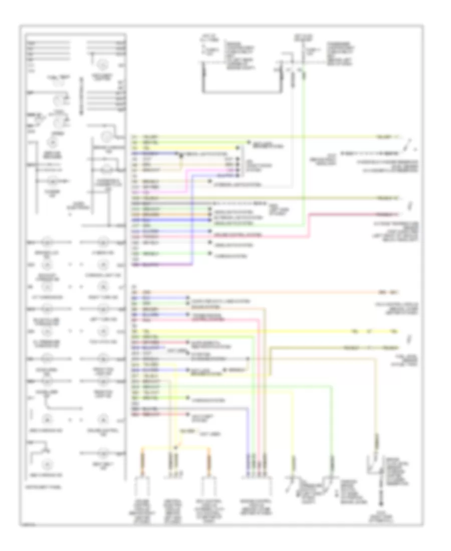
Instrument Cluster Wiring Diagram for Volvo S40 2000
List of elements for Instrument Cluster Wiring Diagram for Volvo S40 2000:
- (not used)
- A/t warning ind
- A10
- A11
- A12
- A13
- A14
- A15
- A16
- A17
- A18
- A19
- A20
- A21
- A22
- A23
- A24
- Abs warning ind
- Air conditioning system
- Anti-lock brakes system
- Anti-theft system
- B10
- B11
- B12
- B13
- B14
- B15
- B16
- B17
- B18
- B19
- B20
- B21
- B22
- B23
- B24
- Brake fluid ind
- Brake fluid level sensor (in brake master cylinder reservoir)
- Brake warning ind
- Bulb failure warning ind
- Central electric module (behind left end of dash)
- Charge ind
- Computer data lines system
- Cruise control ind
- Cruise control module (behind right center of dash)
- Cruise control system
- Door open ind
- E10
- Ecc control module (integral with a/c control, in center of dash)
- Engine compartment fuse & relay box (in left rear corner of engine compt)
- Engine control module (behind lower center of dash)
- Exhaust warning ind
- Exterior lights system
- Front fog lamp ind
- Fuel level sensor (in fuel tank)
- Fuse 11 10a
- Fuse 5 10a
- G107 (behind right headlamp)
- G123 (right side of firewall)
- G202 (left side of dash)
- Headlights system
- Hi beam ind
- Hot at all times
- Hot in on or start
- Immobilizer ind
- Instrument panel
- Instument lighting
- Interior lights system
- Left turn ind
- Micro electronic
- Micro-controlller
- Nca
- Oil pressure switch (left side of eng compt)
- Oil pressure warning ind
- Outside temperature sensor (trip computer) (left front of vehicle, below headlight)
- Parking brake switch (at base of parking brake lever)
- Passenger compartment fuse & relay box (behind left end of dash)
- Pnk
- Rear fog lamp ind
- Right turn ind
- Seat belt ind
- Service reminder
- Sound system
- Speed
- Srs warning ind
- Starting/ charging system
- Tach
- Temp fuel
- Tow hitch ind
- Transmissions control system
- Vgla control module (behind lower center of dash)
- Warning light ind
- Warning system
- Windshield washer fluid ind
- Windshield washer reservoir level sensor (in washer fluid reservoir)
INTERIOR LIGHTS
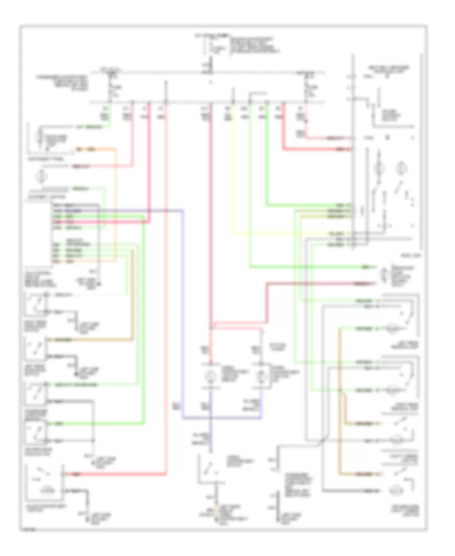
Courtesy Lamps Wiring Diagram, with Reading Lights for Volvo S40 2000
List of elements for Courtesy Lamps Wiring Diagram, with Reading Lights for Volvo S40 2000:
- (left rear side of cargo compartment) g404
- (left side of dash) g202
- A17
- A19
- A23
- A24
- A25
- B21
- Cargo compartment lighting (sedan)
- Cargo compartment lighting (x2)
- Cargo compartment switch
- Courtesy lighting
- Door open indicator lamp
- Driver's door door switch
- Driver's side vanity mirror lighting
- E10
- Engine compartment fuse & relay box (in left rear corner of engine compartment)
- Fuse 10a
- Fuse 15a
- Fuse 5 10a
- G11
- G14
- G22
- Glove compartment lighting
- Hot at all times
- Hot in on
- Instrument panel
- J14
- Left rear door door switch
- Left rear reading lamp
- Nca
- Passenger compartment fuse & relay box (behind left end of dash)
- Passenger door door switch
- Pnk
- Power sun roof switch
- Rear roof lamp (station wagon only)
- Red
- Right rear door door switch
- Right rear reading lamp
- Roof lamp
- Seat belt reminder indicator lamp
- Station wagon
- Vanity mirror lighting
- Vgla control module (behind lower center of dash)
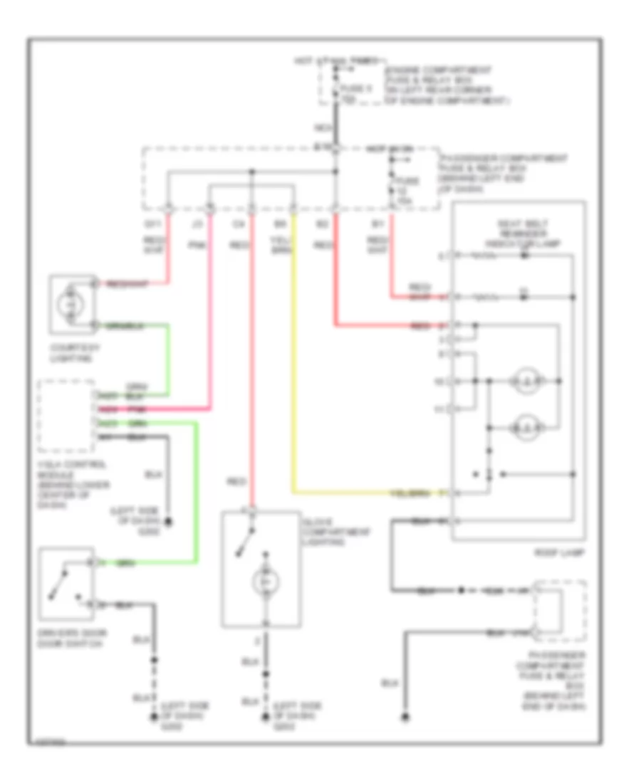
Courtesy Lamps Wiring Diagram, without Reading Lights for Volvo S40 2000
List of elements for Courtesy Lamps Wiring Diagram, without Reading Lights for Volvo S40 2000:
- (left side of dash) g202
- A23
- A24
- A25
- Courtesy lighting
- Driver's door door switch
- E10
- Engine compartment fuse & relay box (in left rear corner of engine compartment)
- Fuse 15a
- Fuse 5 10a
- G11
- Glove compartment lighting
- Hot at all times
- Hot in on
- J14
- Nca
- Passenger compartment fuse & relay box (behind left end of dash)
- Pnk
- Red
- Roof lamp
- Seat belt reminder indicator lamp
- Vgla control module (behind lower center of dash)
Instrument Illumination Wiring Diagram for Volvo S40 2000
List of elements for Instrument Illumination Wiring Diagram for Volvo S40 2000:
- (center of dash) g206
- (door lock opening) distribution rail
- (left side of dash) g202
- +15
- 58d
- A13
- Ashtray lighting
- Automatic transmission gear selector position lighting
- Blower motor fan controls
- C12
- Central electric module (cem) (behind left end of dash)
- Central locking switch (sedan)
- Central locking switch (station wagon)
- D11
- Dimmer
- Distribution ground terminal
- Fuse 6 20a
- Heater controls (lighting) (electronic climate control)
- Heater controls lighting (manual climate control)
- Hot in on
- Illumination
- Instrument lighting
- Light switch
- P14
- P15
- Passenger air bag switch (except usa models)
- Passenger air bag switch (usa models)
- Passenger compartment fuse & relay box (behind left end of dash)
- Radio
- Rear door lock switch
- Sedan
- Station wagon
POWER ANTENNA
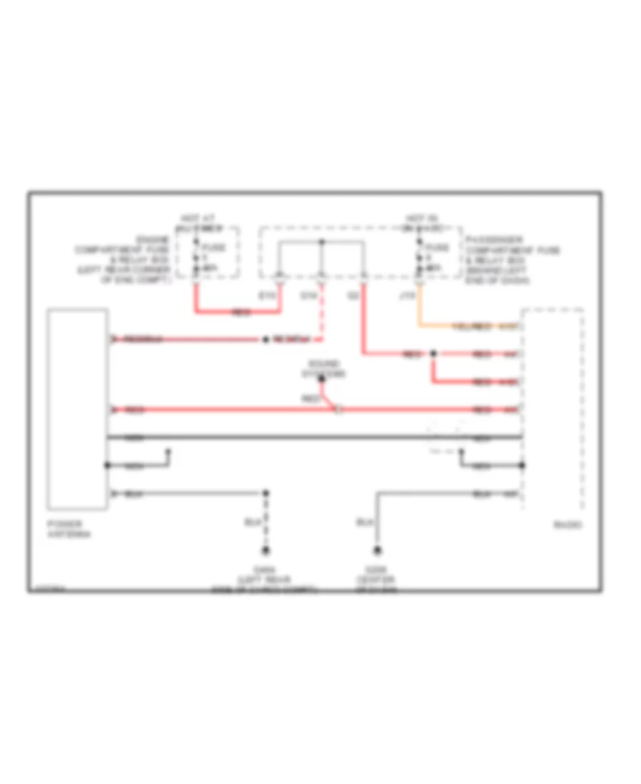
Power Antenna Wiring Diagram for Volvo S40 2000
List of elements for Power Antenna Wiring Diagram for Volvo S40 2000:
- A12
- A13
- E10
- Engine compartment fuse & relay box (left rear corner of eng compt)
- Fuse 10a
- Fuse 15a
- G14
- G206 center of dash)
- G404 (left rear side of cargo compt)
- Hot at all times
- Hot in on & acc
- J10
- Nca
- Passenger compartment fuse & relay box (behind left end of dash)
- Power antenna
- Radio
- Red
- Sound systems
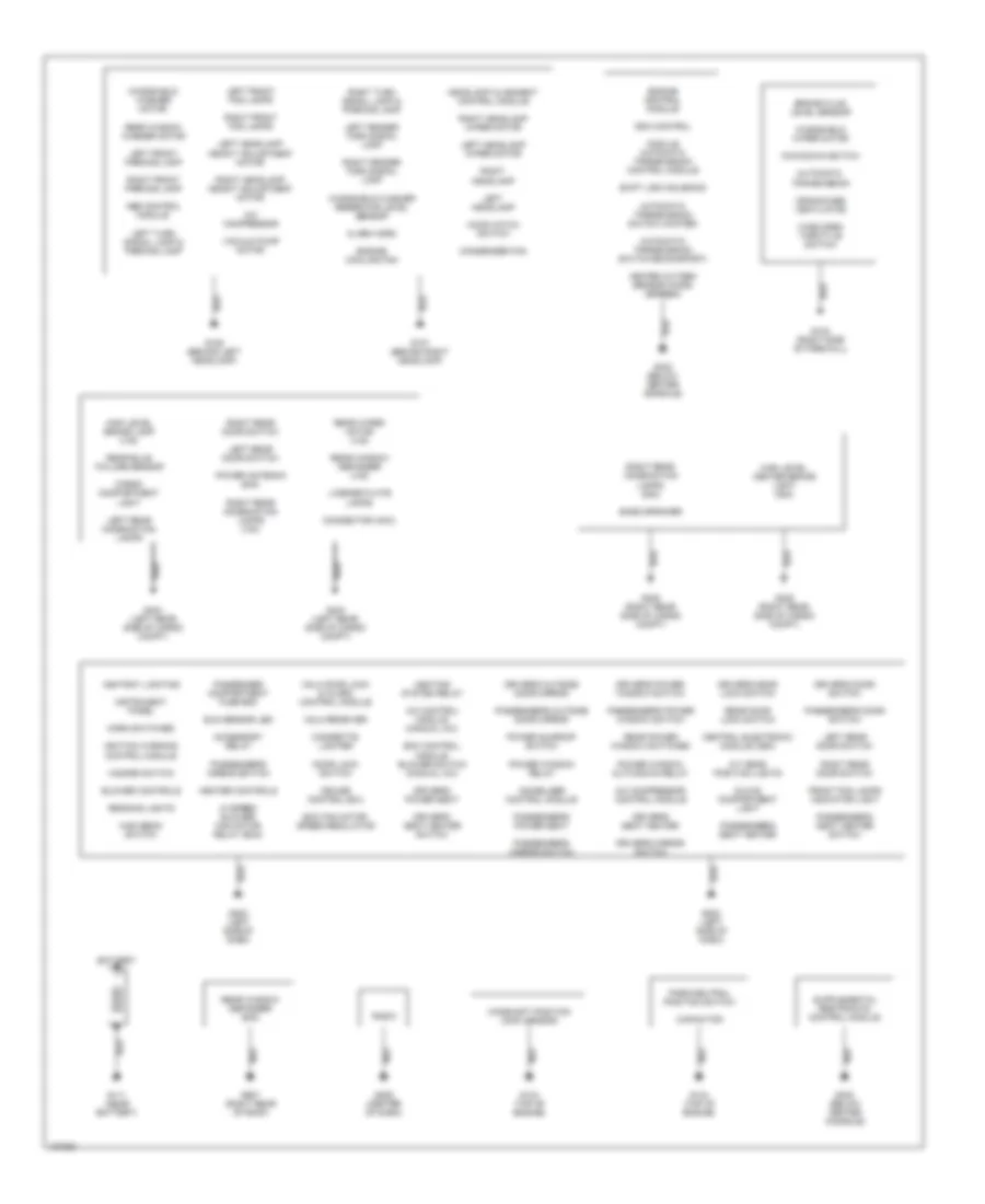
POWER DISTRIBUTION
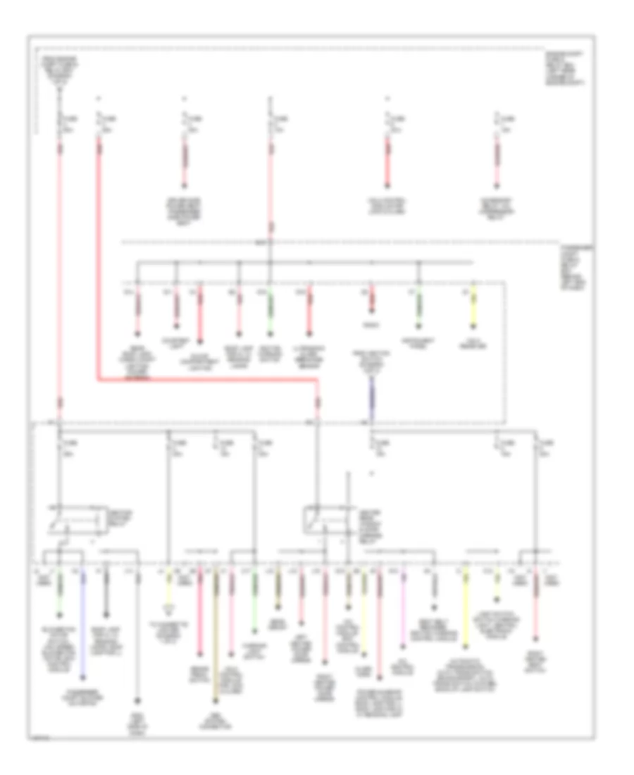
Power Distribution Wiring Diagram (1 of 3) for Volvo S40 2000
List of elements for Power Distribution Wiring Diagram (1 of 3) for Volvo S40 2000:
- Abs control module
- Accessory relay (in passenger compartment fuse & relay box)
- Alarm horn
- Battery
- Brake pedal switch for locking gear shift selector
- Central electronic module (cem)
- Cigarette lighter
- Engine compartment fuse & relay box (on left rear corner of engine compt)
- Engine cooling fan, a/c condenser fan
- From passenger compt fuse & relay box (diagram 2 of 3)
- From passenger compt fuse & relay box (diagram 3 of 3)
- Fuel pump
- Fuel system relay
- Fuse 10a
- Fuse 120a
- Fuse 15a
- Fuse 20a
- Fuse 30a
- Fuse 40a
- Fuse 50a
- G111 (near battery)
- G202 (left side of dash)
- Generator
- Immobilizer control module, fuel system relay, engine control module, automatic transmission control module (tcu)
- Pnk
- Power windows
- Pressure switch vacuum pump ems 2000 turbo
- Red
- Starter
- To engine compt fuse & relay box (diagram 2 of 3)
- To ignition switch (diagram 3 of 3)
- Vacuum pump ems 2000 turbo
Power Distribution Wiring Diagram (2 of 3) for Volvo S40 2000
List of elements for Power Distribution Wiring Diagram (2 of 3) for Volvo S40 2000:
- (not used)
- A/c control module
- A/c control module, ecc control module
- Accessory relay, a/c compressor relay
- Alarm horn
- Automatic transmission, auto trans switch (econo/sport), auto trans switch (winter), back-up lamp switch
- Blower fan motor switch, max speed blower fan motor, ecc control module
- Brake pedal switch
- C12
- C17
- Courtesy light
- Driver side power seat, passenger side power seat
- E10
- Engine compt fuse & relay box (left rear corner of engine compt)
- From engine compt fuse & relay box (diagram 1 of 3)
- From ignition switch (diagram 3 of 3)
- Fuse 10a
- Fuse 15a
- Fuse 20a
- Fuse 25a
- Fuse 30a
- Fuse 50a
- G11
- G12
- G13
- G14
- G15
- G16
- G202 (left side of dash)
- Glove compartment lighting
- Heated rear window & door mirrors relay
- Heating system relay
- I18
- Ignition warning switch
- Instrument panel
- J14
- J15
- J16
- J18
- Left heated power door mirror
- Light switch, switch warning light, central electronic module
- Obd system connector
- Passenger compt blower motor fan
- Passenger compt fuse & relay box (behind left end of dash)
- Pnk
- Power sunroof control module, roof lamp for ll, roof lamp for hl w/ reading lamp
- Radio
- Rear demist
- Rear roof lamp, cargo compt lighting, power antenna
- Red
- Right heated power door mirror
- Right heated seat switch
- Roof lamp for hl w/ reading lamps
- Roof lamp for hl w/ reading lamps, roof lamp for ll
- Seat belt reminder, ignition warning control module
- To cigarette lighter (diagram 1 of 3)
- Ultrasonic glass breakage sensor
- Vgla control module for lock & alarm
- Vgla receiver
- Warning light switch
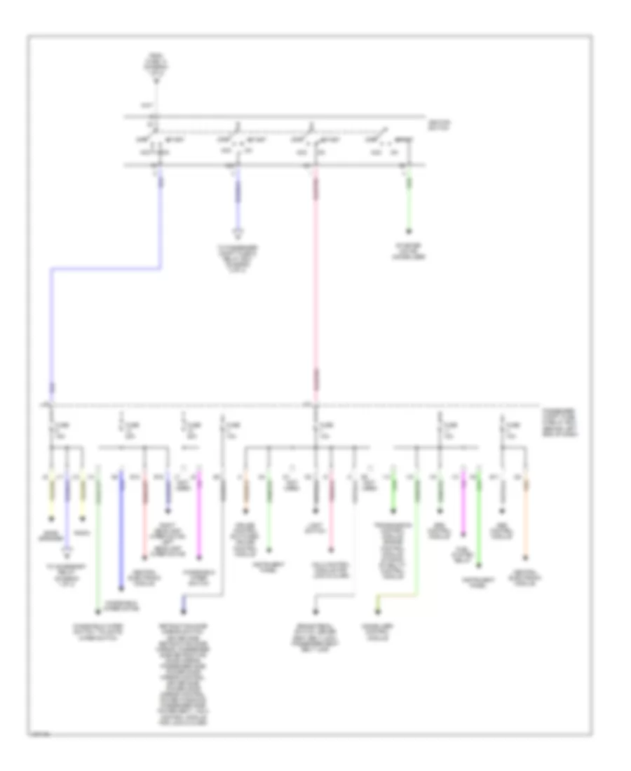
Power Distribution Wiring Diagram (3 of 3) for Volvo S40 2000
List of elements for Power Distribution Wiring Diagram (3 of 3) for Volvo S40 2000:
- (not used)
- 15/1
- 15/2
- Abs control module
- Acc
- Bass speaker
- Brake pedal switch, driver seat belt lock, passenger seat belt lock
- Central electronic module
- Cruise control switches, cruise control module
- E11
- E13
- E15
- From fuse 14 (diagram 1 of 3)
- Fuel system relay
- Fuse 10a
- Fuse 15a
- Fuse 20a
- I12
- I13
- I14
- I15
- I16
- I22
- Ignition switch
- Immobilizer control module
- Instrument panel
- J10
- J11
- J12
- Light switch
- Off
- Passenger compt fuse & relay box (behind left end of dash)
- Radio
- Retracting door mirror switch, driver side retracting door mirror, passenger side retracting door mirror, passenger side power door mirror control, driver side power door mirror control, power windows, passenger side power seat, vgla control module for lock & alarm
- Right headlamp wiper motor, left headlamp wiper motor
- Srs control module
- Start
- Starter motor (immobilizer)
- To accessory relay (diagram 1 of 3)
- To passenger compt fuse & relay box (diagram 2 of 3)
- Transmission control module, engine control module, dynamic stability control module
- Vgla control module for lock & alarm
- Windshield wiper motor
- Windshield wiper switch
- Windshield wiper switch, tailgate wiper switch
POWER DOOR LOCKS
Power Door Lock Wiring Diagram, with Remote Control System for Volvo S40 2000
List of elements for Power Door Lock Wiring Diagram, with Remote Control System for Volvo S40 2000:
- (behind lower center of dash) vgla control module
- A10
- A11
- B10
- B11
- C10
- Cargo compartment switch
- Computer data lines
- Door lock switch
- Driver door switch
- Driver's door lock motor
- Driver's door lock switch
- E10
- Engine compartment fuse & relay box (in left rear corner of engine compt)
- Exterior lights system
- F10
- Fuel tank lock motor
- Fuse 10a
- Fuse 20a
- G15
- G202 (left side of dash)
- G404 (left rear side of cargo compt)
- Hot at all times
- Hot in start & on
- Ignition warning switch
- Interior lights system
- J/c (left side of dash)
- Left rear door switch
- Left rear lock motor
- Nca
- Passenger compartment fuse & relay box (behind left end of dash)
- Passenger door lock motor
- Passenger door switch
- Pnk
- Red
- Red/
- Right rear door lock motor
- Right rear door switch
- Tailgate/cargo door lock motor
- Vgla receiver (in rear of engine compt)
Power Door Lock Wiring Diagram, without Remote Control System for Volvo S40 2000
List of elements for Power Door Lock Wiring Diagram, without Remote Control System for Volvo S40 2000:
- A10
- Driver door lock switch
- Engine compartment fuse & relay box (in left rear corner of engine compt)
- Fuel tank lock motor
- Fuse 20a
- G202 (left side of dash)
- Hot at all times
- J/c (left side of dash)
- Left rear lock motor
- Passenger door lock motor
- Red
- Right rear door lock motor
- Tailgate/cargo door lock motor
- Vgla control module (behind lower center of dash)
POWER MIRRORS
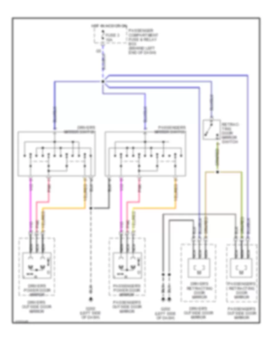
Power Mirror Wiring Diagram for Volvo S40 2000
List of elements for Power Mirror Wiring Diagram for Volvo S40 2000:
- Driver's mirror switch
- Driver's outside door mirror
- Driver's power door mirror
- Driver's retracting door mirror
- Fuse 3 10a
- G202 (left side of dash)
- Hot in acc or on
- Nca
- Passenger compartment fuse & relay box (behind left end of dash)
- Passenger's mirror switch
- Passenger's outside door mirror
- Passenger's power door mirror
- Passenger's retracting door mirror
- Pnk
- Retrac- ting door mirror switch
POWER SEATS
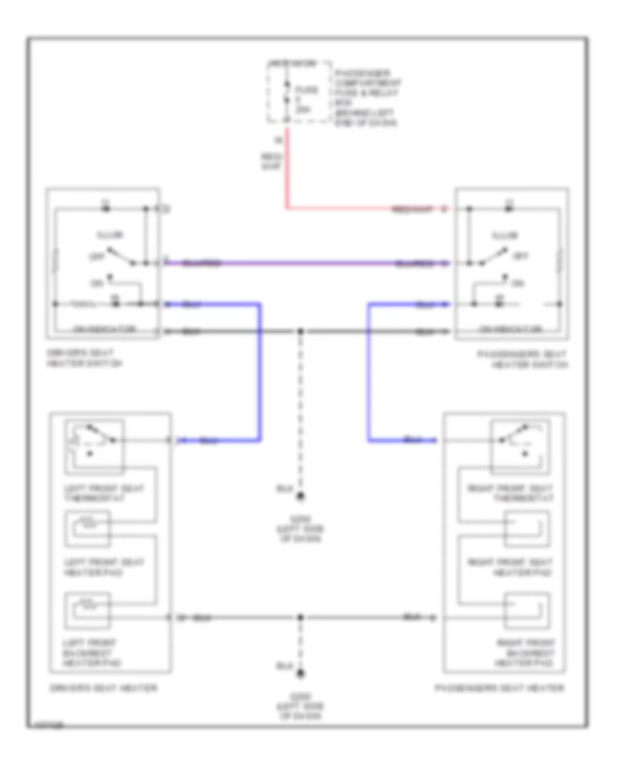
Heated Seats Wiring Diagram for Volvo S40 2000
List of elements for Heated Seats Wiring Diagram for Volvo S40 2000:
- Backrest
- Driver's seat heater
- Driver's seat heater switch
- Fuse 20a
- G202 (left side of dash)
- Heater pad
- Hot in on
- Illum
- Left front backrest heater pad
- Left front seat thermostat
- Left front seat heater pad
- Off
- On indicator
- Passenger compartment fuse & relay box (behind left end of dash)
- Passenger's seat heater
- Passenger's seat heater switch
- Right front
- Right front seat
- Right front seat
- Thermostat
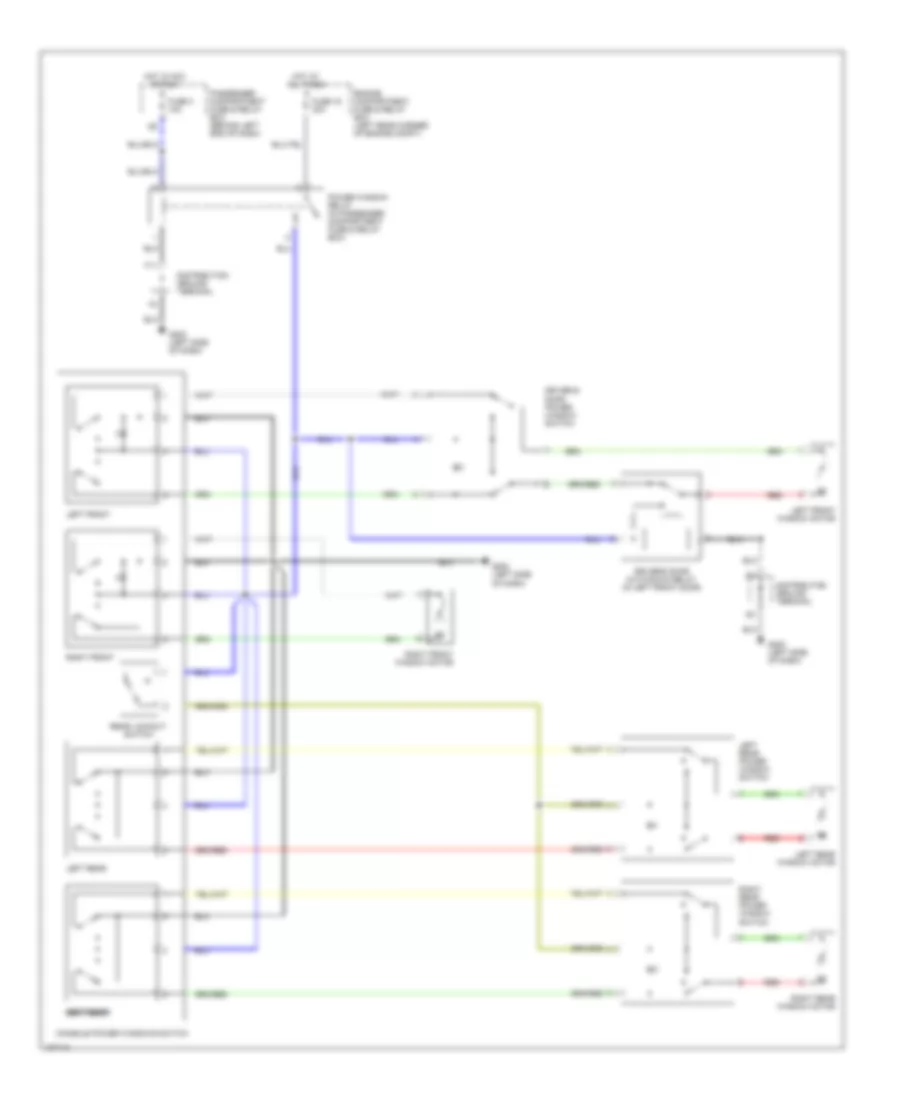
Power Seats Wiring Diagram for Volvo S40 2000
List of elements for Power Seats Wiring Diagram for Volvo S40 2000:
- Aft
- Back
- Back rest
- Backrest motor
- Down
- Driver's power seat
- Engine compartment fuse & relay box (in left rear corner of engine compt)
- Fore
- Fore/ aft
- Forw
- Forward/ backward motor
- Front edge
- Front edge up/down motor
- Fuse 3 10a
- Fuse 4 30a
- G202 (left side of dash)
- Hot at all times
- Hot in acc or on
- Nca
- Passenger compartment fuse & relay box (behind left end of dash)
- Passenger's power seat
- Rear edge
- Rear edge up/down motor
- Solid state
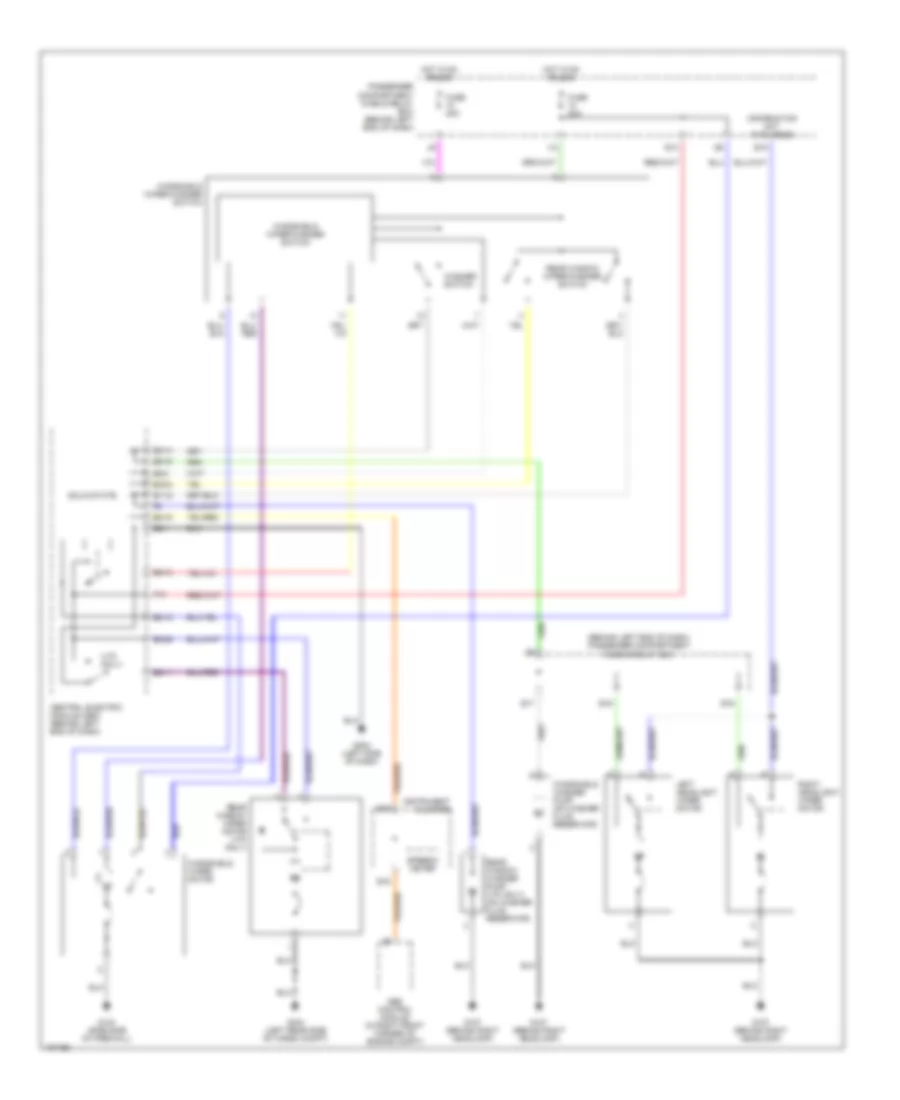
POWER TOP/SUNROOF
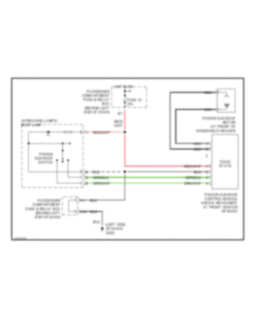
Power Top/Sunroof Wiring Diagrams for Volvo S40 2000
List of elements for Power Top/Sunroof Wiring Diagrams for Volvo S40 2000:
- (left side of dash) g202
- (w/reading lamps) roof lamp
- Fuse 12 15a
- Hot in on
- J14
- Nca
- Passenger compartment fuse & relay box (behind left end of dash)
- Power sun roof control module (above headliner, at front center of roof)
- Power sun roof motor (at front of windshield header
- Power sun roof switch
- Solid state
POWER WINDOWS
Power Window Wiring Diagram for Volvo S40 2000
List of elements for Power Window Wiring Diagram for Volvo S40 2000:
- Console power windows switch
- Distribution ground terminal
- Driver's door auto-down relay (in left front door)
- Driver,s door power window switch
- Engine compartment fuse & relay box (left rear corner of engine compt)
- F11
- Fuse 16 30a
- Fuse 3 10a
- G202 (left side of dash)
- Hot at all times
- Hot in acc or run
- Left front
- Left front window motor
- Left rear
- Left rear power window switch
- Left rear window motor
- Passenger compartment fuse & relay box (behind left end of dash)
- Power window relay (in passenger compartment fuse & relay box)
- Rear lockout switch
- Red
- Right front
- Right front window motor
- Right rear left rear
- Right rear power window switch
- Right rear window motor
RADIO
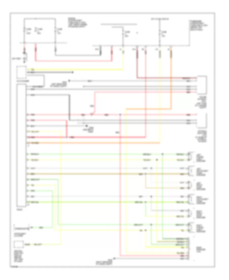
Radio Wiring Diagrams for Volvo S40 2000
List of elements for Radio Wiring Diagrams for Volvo S40 2000:
- (left side of luggage compt)
- (s40)
- Amplifier (v40) (at base of antenna, on roof)
- Antenna
- B2/b3
- Bass speaker (v40)
- Battery
- C/d changer
- Central electric module (behind left end of dash)
- Din cable
- E10 nca
- Engine compartment fuse & relay box (left rear corner of engine compt)
- Fuse 10a
- Fuse 120a
- Fuse 15a
- Fuse 20a
- Fuse 50a
- G2 red
- G206 (center of dash)
- G404 (left rear side of cargo compt)
- G405 (right rear side of cargo compt)
- Hot in acc and on
- Instrument cluster
- Left front door speaker
- Left instrument panel speaker
- Left parcel shelf speaker
- Nca
- Passenger compartment fuse & relay box (behind left end of dash)
- Power antenna
- Radio
- Red
- Right front door speaker
- Right instrument panel speaker
- Right parcel shelf speaker
- Speedometer
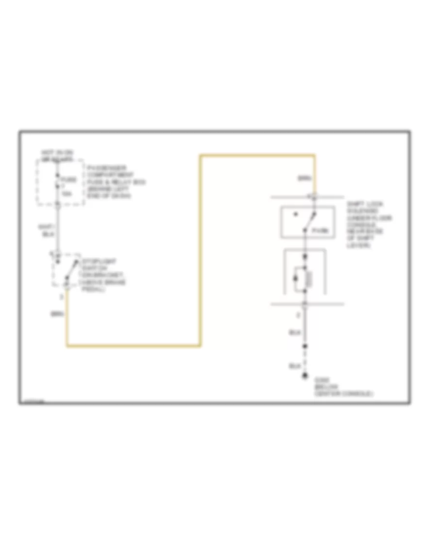
SHIFT INTERLOCKS
Shift Interlock Wiring Diagram for Volvo S40 2000
List of elements for Shift Interlock Wiring Diagram for Volvo S40 2000:
- Fuse 10a
- G302 (below center console)
- Hot in on or start
- Park
- Passenger compartment fuse & relay box (behind left end of dash)
- Shift lock solenoid (under floor console, near base of shift lever)
- Stoplight switch (on bracket, above brake pedal)
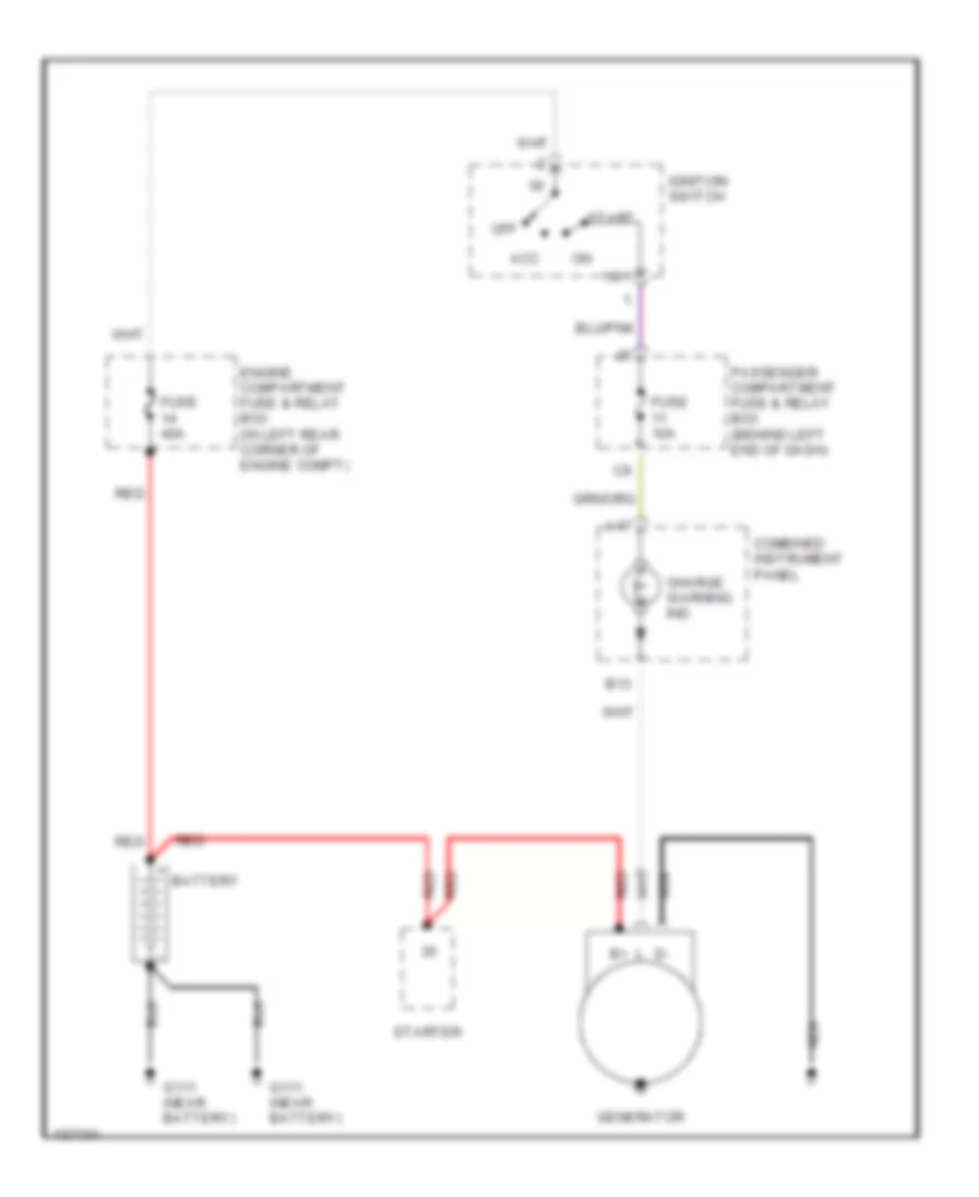
STARTING/CHARGING
Charging Wiring Diagram for Volvo S40 2000
List of elements for Charging Wiring Diagram for Volvo S40 2000:
- 15/1
- A17
- Acc
- B13
- Battery
- Charge warning ind
- Combined instrument panel
- Engine compartment fuse & relay box (in left rear corner of engine compt)
- Fuse 10a
- Fuse 40a
- G111 (near battery)
- Generator
- Ignition switch
- Nca
- Off
- Passenger compartment fuse & relay box (behind left end of dash)
- Red
- Start
- Starter
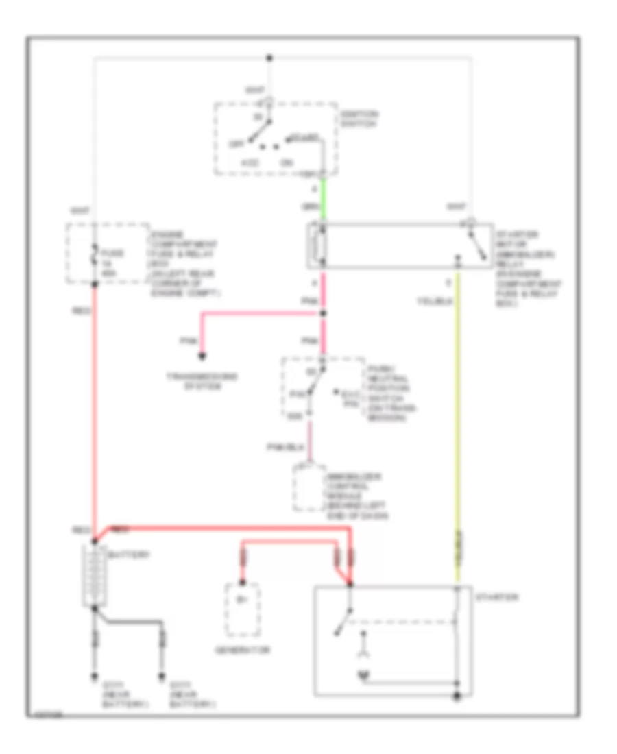
Starting Wiring Diagram for Volvo S40 2000
List of elements for Starting Wiring Diagram for Volvo S40 2000:
- 15/1
- 50s
- Acc
- Battery
- Engine compartment fuse & relay box (in left rear corner of engine compt)
- Exc p/n
- Fuse 40a
- G111 (near battery)
- Generator
- Ignition switch
- Immobilizer control module (behind left end of dash)
- Off
- P/n
- Park/ neutral position switch (on trans- mission)
- Pnk
- Red
- Start
- Starter
- Starter motor (immobilizer) relay (in engine compartment fuse & relay box)
- Transmissions system
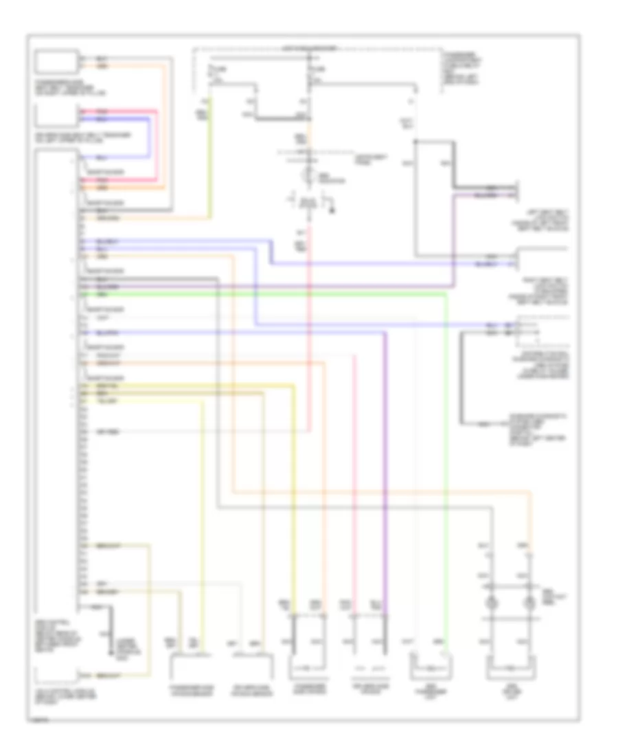
SUPPLEMENTAL RESTRAINTS
Supplemental Restraint Wiring Diagram for Volvo S40 2000
List of elements for Supplemental Restraint Wiring Diagram for Volvo S40 2000:
- (under center console) g302
- A10
- A17
- B11
- Distribution rail on-board diagnostic (obd) system (in relay holder, under dash-board)
- Driver's side air bag
- Driver's side air bag sensor
- Driver's side seat belt tensioner (on left upper "b" pillar)
- Fuse 10a
- Hot in run or start
- I16
- Instrument panel
- Left seat belt lock switch (inside of left front seat belt buckle)
- Nca
- On-board diagnostic system (obd) connector (partial) (behind left center of dash)
- Passenger compartment fuse & relay box (behind left end of dash)
- Passenger side air bag
- Passenger side air bag sensor
- Passenger's side seat belt tensioner (on right upper "b" pillar)
- Pnk
- Right seat belt lock switch (if equipped) (inside of right front seat belt buckle)
- Shorting bar
- Solid state
- Srs contact reel
- Srs control module (below rear of center console, between front seats)
- Srs driver unit
- Srs indicator
- Srs passenger unit
- Vgla control module (behind lower center of dash)
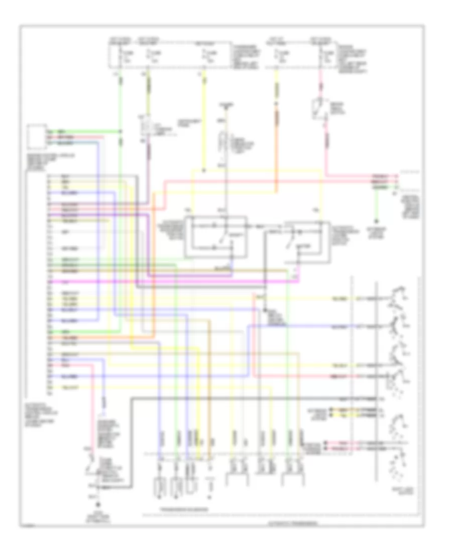
TRANSMISSION
A/T Wiring Diagram for Volvo S40 2000
List of elements for A/T Wiring Diagram for Volvo S40 2000:
- 15i
- 50s
- A/t warning lamp
- A17
- Automatic transmission
- Automatic transmission control module (behind lower center of dash)
- Automatic transmission econ/sport position switch
- Automatic transmission winter position switch
- Brake pedal switch
- Central electric module (behind left end of dash)
- Dimmer
- Engine compartment fuse & relay box (on left rear corner of engine compt)
- Engine control module (behind lower center of of dash)
- Exterior lights system
- Fuse 10a
- Fuse 15a
- Fuse 20a
- G123 (right side of firewall)
- G302 (below center console)
- Gear selector position light
- Hot at all times
- Hot in on
- Hot in run or start
- I14
- Instrument panel
- Nca
- On-board diagnostic system connector (beneath center of dash)
- Passenger compartment fuse & relay box (behind left end of dash)
- Pnk
- Shift lock switch
- Sporty
- Starting/ charging system
- Sth
- Sthg
- Transmission solenoids
- Wide open throttle switch (rear of eng compt)
- Winter
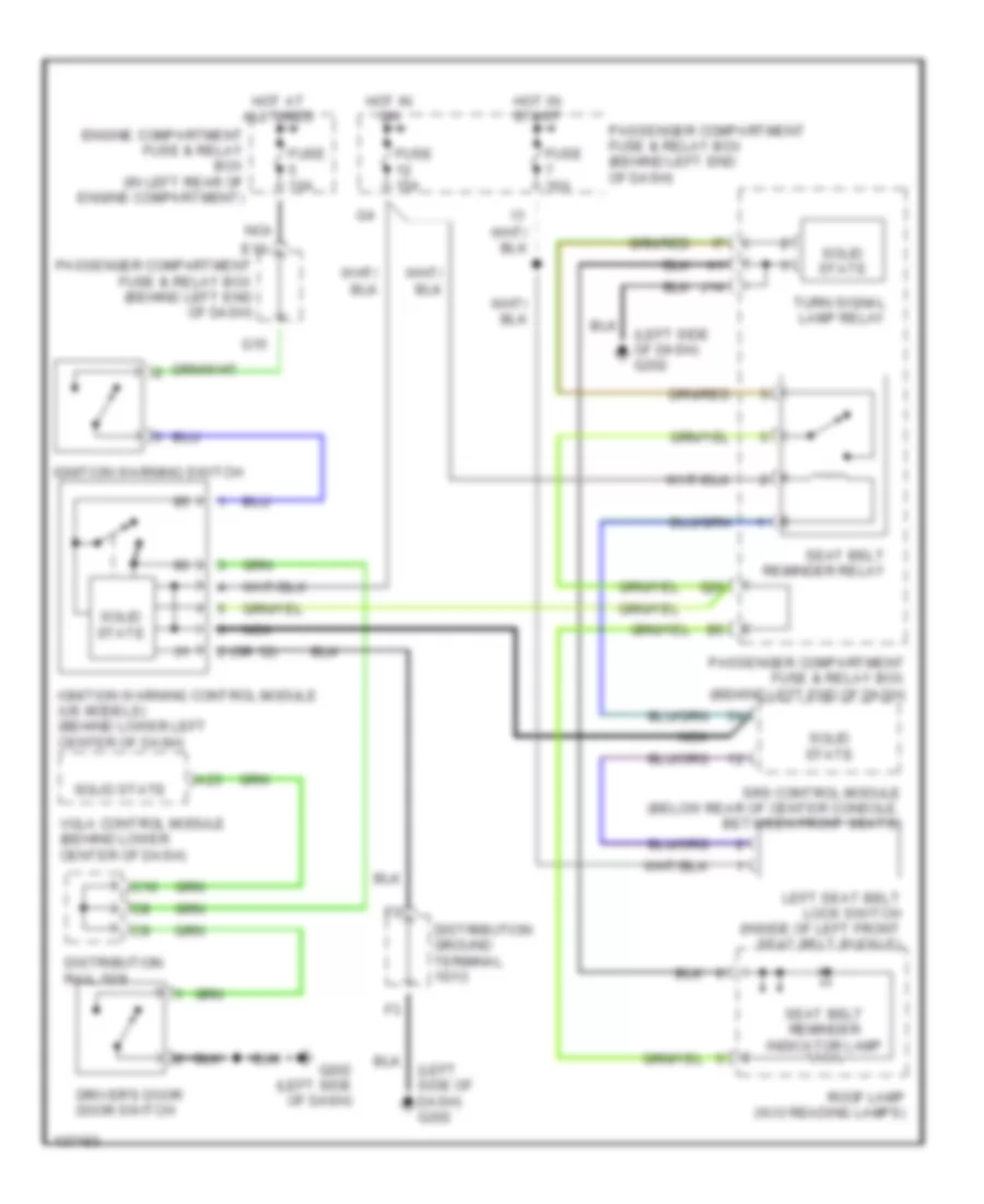
WARNING SYSTEMS
Warning System Wiring Diagrams for Volvo S40 2000
List of elements for Warning System Wiring Diagrams for Volvo S40 2000:
- (left side of dash) g202
- 2 (or 12)
- A23
- C10
- Distribution ground terminal 15/13
- Distribution rail 15/9
- Driver's door door switch
- E10
- Engine compartment fuse & relay box (in left rear of engine compartment)
- Fuse 10a
- Fuse 15a
- G15
- G20
- G202 (left side of dash)
- Hot at all times
- Hot in on
- Hot in start
- Ignition warning control module (us models) (behind lower left center of dash)
- Ignition warning switch
- J14
- Left seat belt lock switch (inside of left front seat belt buckle)
- Nca
- Passenger compartment fuse & relay box (behind left end of dash)
- Roof lamp (w/o reading lamps)
- Seat belt reminder indicator lamp
- Seat belt reminder relay
- Solid state
- Srs control module (below rear of center console, between front seats)
- Turn signal lamp relay
- Vgla control module (behind lower center of dash)
WIPER/WASHER
Wiper/Washer Wiring Diagram for Volvo S40 2000
List of elements for Wiper/Washer Wiring Diagram for Volvo S40 2000:
- (behind left end of dash) passenger compartment fuse & relay box
- (information not available)
- (v70 only)
- Abs control module (in right front corner of engine compt)
- B1/12
- B16
- B2/1
- B2/11
- B2/12
- B2/13
- B2/14
- B2/15
- B2/16
- B2/2
- B2/24
- B2/26
- Central electric module (cem) (behind left end of dash)
- E13
- E15
- E16
- E17
- E19
- F10
- Fuse 20a
- G107 (behind right headlamp)
- G123 (ride side of firewall)
- G202 (left side of dash)
- G404 (left rear side of cargo compt)
- Hot in on or acc
- I12
- Instrument cluster
- Left headlight wiper motor
- Passenger compartment fuse & relay box (behind left end of dash)
- Rear window washer pump (v70 only) (on washer fluid reservoir)
- Rear window wiper motor (v70 only)
- Rear window wiper/washer switch
- Right headlight wiper motor
- Solid state
- Speedo- meter
- Washer switch
- Windshield washer pump (on washer fluid reservoir)
- Windshield wiper motor
- Windshield wiper/washer switch

 Čeština
 Dansk
Dansk Deutsch
 Ελληνικά
 English
 Español
 Suomi
Suomi Français
 Français
 עברית
עברית Hrvatski
 Magyar
 Italiano
 日本語
日本語 한국어
한국어 Nederlands
 Polski
 Português
 Português
 Română
 Русский
 Slovenčina
 Slovenščina
 Svenska
 Türkçe
 中文 (中国)