ANTI-LOCK BRAKES
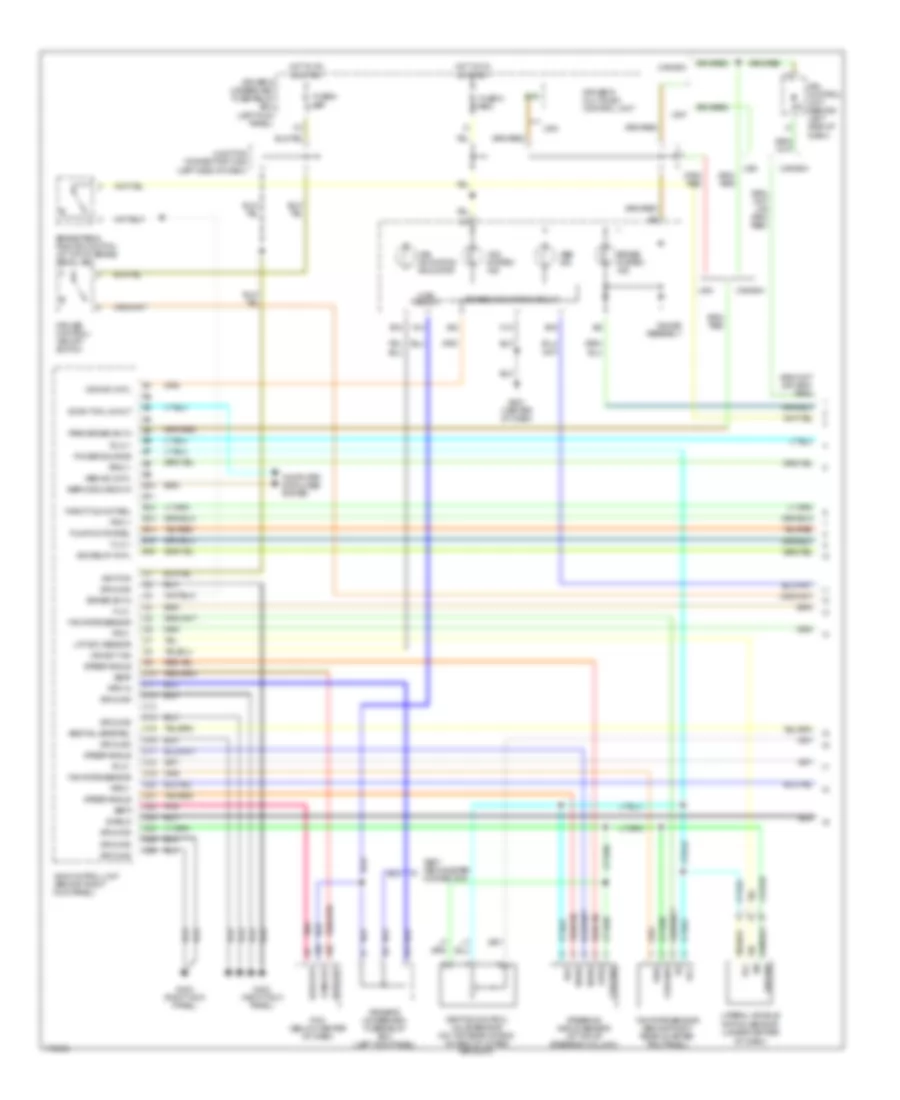
Anti-lock Brakes Wiring Diagram, Except Type S (1 of 2) for Acura 3.2TL 2003
 https://portal-diagnostov.com/license.html
Automotive Electricians Portal FZCO
Automotive Electricians Portal FZCO
https://portal-diagnostov.com/license.html
https://portal-diagnostov.com/license.html
Automotive Electricians Portal FZCO
Automotive Electricians Portal FZCO
List of elements for Anti-lock Brakes Wiring Diagram, Except Type S (1 of 2) for Acura 3.2TL 2003:
- (behind driver's dashboard lower cover) brake pedal position switch
- (behind left end of dash)
- (behind lower left side of dash) junction connector c452
- (not
- (not used)
- (or
- A/t pos sw
- A10
- A11
- A12
- A13
- A14
- A15
- A16
- A17
- A18
- A19
- A20
- A21
- A22
- A23
- A24
- A25
- A26
- A29
- Abs ind
- Abs ind light
- Abs indicator circuit
- Abs pump ck
- Abs/tcs control unit (behind right kick panel)
- B10
- B11
- B12
- B13
- B14
- B15
- B16
- B4
- Brake fluid level switch (integral to brake fluid reservoir cap)
- Brake sw in
- Brake system ind light
- C10
- C11
- C12
- C16
- C4
- Canada
- Computer data lines system
- Cruise control/ tcs switch
- Driver's multiplex control unit
- Driver's under- dash fuse/ relay box (behind left end of dash)
- Driver's underdash fuse/relay box
- Driver's underdash fuse/relay box (behind left end of dash)
- Drl control unit (behind left side of dash)
- E16
- E17
- Engine retard
- Fail-safe rly
- Fl in
- Fl out
- Flw (+)
- Flw (-)
- Fr in
- Fr out
- Frw (+)
- Frw (-)
- Fuse 4 7.5a
- Fuse 47 20a
- Fuse 6 15a
- Fuse 9 7.5a
- G101 (on rear of left cylinder head)
- G302 (at left rear of engine compt)
- G402 (behind right kick panel)
- G403 (behind right kick panel)
- G501 (below center of dash)
- Gauge assembly
- Ground
- Hot at all time
- Hot in on
- Hot in on or start
- I12
- Ign in
- K10
- K14 usa
- Left front wheel speed sensor
- Left rear wheel speed sensor
- Main circuit
- Ncl
- Ncr
- Nol
- Nor
- O10
- O15
- Park brake
- Parking brake switch (on parking brake pedal bracket)
- Passenger's underdash fuse/relay box (behind right end of dash)
- Pcm (behind center of dash)
- Pnk
- Pump mtr ck
- Q9 canada
- Ref voltage
- Retard req
- Right front wheel speed sensor
- Right rear wheel speed sensor
- Rl in
- Rl out
- Rlw (+)
- Rlw (-)
- Rpm in
- Rpm out
- Rr in
- Rr out
- Rrw (+)
- Rrw (-)
- Scan in/out
- Svc check
- Tcs 1
- Tcs 2
- Tcs ind light
- Tcs per in
- Tcs per out
- Tcs rly ctrl
- Tcs switch in
- Test tachometer connector
- Throttle pos
- Underhood fuse/relay box (on right side of firewall)
- Usa
- Used)
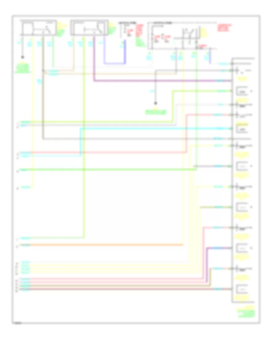
Anti-lock Brakes Wiring Diagram, Except Type S (2 of 2) for Acura 3.2TL 2003
List of elements for Anti-lock Brakes Wiring Diagram, Except Type S (2 of 2) for Acura 3.2TL 2003:
- Abs fail-safe relay (in abs relay box)
- Abs pump motor
- Abs pump motor relay
- Abs/tcs modulator unit (on right rear of engine compartment)
- Fuse 20a
- Fuse 40a
- Fuse 63 7.5a
- G202 (at lower right rear of engine compartment)
- G203 (behind right side of front bumper)
- Hot at all times
- Left front abs solenoid (in)
- Left front abs solenoid (out)
- Left rear abs solenoid (in)
- Left rear abs solenoid (out)
- Left tcs solenoids
- Right front abs solenoid (in)
- Right front abs solenoid (out)
- Right rear abs solenoid (in)
- Right rear abs solenoid (out)
- Right tcs solenoids
- Tcs relay (in tcs relay box)
- Under hood fuse/ relay box (on right side of firewall)
- Underhood abs fuse/ relay box
Anti-lock Brakes Wiring Diagram, Type S (1 of 3) for Acura 3.2TL 2003
List of elements for Anti-lock Brakes Wiring Diagram, Type S (1 of 3) for Acura 3.2TL 2003:
- (left side of dash)
- A13
- A19
- A20
- A22
- Abs fail-safe rel
- Abs ind
- Abs ind cntl
- B10
- B11
- B12
- B13
- B14
- B15
- B16
- B4
- Brake pedal position switch (at top of brake pedal arm
- Brake sw in
- Brake system ind
- C10
- C11
- C12
- C13
- C14
- C15
- C16
- C17
- C18
- C19
- C20
- C21
- C22
- C23
- C24
- C25
- C26
- C4
- Canada
- Computer data lines system
- Cruise control/ vsa off switch
- Data out
- Diag
- Driver's multiplex control unit
- Driver's underdash fuse/relay box (left kick panel)
- Drl control unit (behind left side of dash)
- Flw +
- Flw -
- Frw +
- Frw -
- Fuse 6 15a
- Fuse 9 7.5a
- G402 (right kick panel)
- G403 (right kick panel)
- G501 (center of dash)
- Gauge assembly
- Ground
- Hot in on or start
- I12
- Ignition
- Junction connector c452
- Lat acc sensor
- Lateral accele- ration sensor (under center
- Main circuit
- Of dash)
- Park brake sw in
- Pcm (below center of dash)
- Pnk
- Power source
- Pump motor rel
- Ref
- Rlw +
- Rlw -
- Rpm in
- Rpm out
- Rrw +
- Rrw -
- Scan tool in/out
- Sdiag
- Seaf
- Sefa
- Service check in
- Shield
- Steer angle
- Steering angle sensor (at top of steering column)
- Stra
- Test techometer connector
- Throttle mot rel
- Usa
- Vcc
- Vsa act ind
- Vsa activation indicator
- Vsa control unit (brhind right kick panel)
- Vsa ind cntl
- Vsa relay cntl
- Vsa system ind
- Vsa/abs indicator circuit
- Vsa/tcs control valve sensor (on top rear of eng, on end of intake air duct)
- Yaw rate sensor
- Yaw rate sensor (behind right rear quarter trim panel)
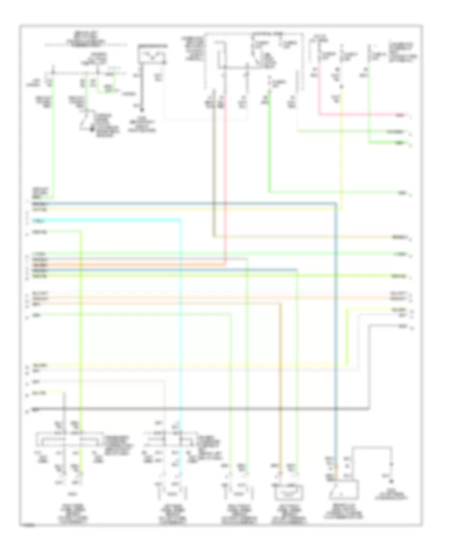
Anti-lock Brakes Wiring Diagram, Type S (2 of 3) for Acura 3.2TL 2003
List of elements for Anti-lock Brakes Wiring Diagram, Type S (2 of 3) for Acura 3.2TL 2003:
- (behind left end of dash) driver's underdash fuse/relay box
- (not used)
- A17
- A18
- Abs pump motor relay
- B13
- B14
- B15
- Brake fluid level switch (integral to brake fluid reservoir cap)
- C11
- C16
- Canada
- Driver's multiplex control unit
- Driver's underdash fuse/relay box (behind left end of dash)
- Fuse 47 20a
- Fuse 48 20a
- Fuse 50 20a
- Fuse 61 40a
- Fuse 62 20a
- Fuse 63 40a
- G203 (behind right side of front bumper)
- G302 (at left rear of engine compt)
- Hot at all times
- K10
- K14
- Left front wheel speed sensor (on left steering knuckle assembly)
- Left rear wheel speed sensor (on left wheel hub assembly)
- O10
- Parking brake switch (on parking brake pedal bracket)
- Passenger's underdash fuse/relay box (behind right end of dash)
- Pnk
- Right front wheel speed sensor (on right steering knuckle assembly)
- Right rear wheel speed sensor (on right wheel hub assembly)
- Underhood abs fuse/ relay box (on right side of firewall)
- Underhood fuse/relay box (on right side of firewall)
- Usa canada
- Vsa pump motor
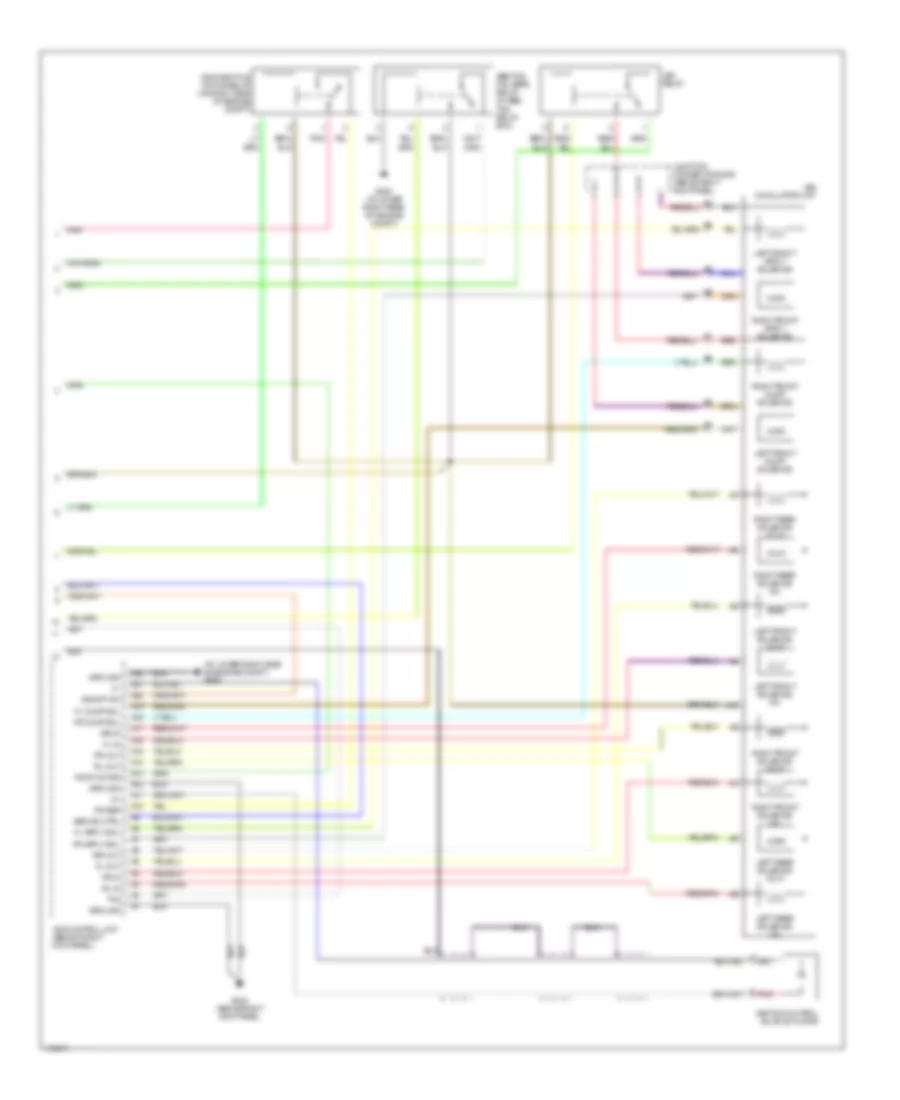
Anti-lock Brakes Wiring Diagram, Type S (3 of 3) for Acura 3.2TL 2003
List of elements for Anti-lock Brakes Wiring Diagram, Type S (3 of 3) for Acura 3.2TL 2003:
- (at lower right side of engine compt) g202
- A10
- A11
- A12
- A13
- A14
- A15
- A16
- A17
- A18
- A19
- A20
- A21
- A22
- Abs ind ctrl
- Abs/tcs fail-safe relay (in abs/ tcs relay box)
- Fl dump sol
- Fl-in
- Fl-out
- Fr dump sol
- Fr-in
- Fr-out
- G202 (at lower right rear of engine compt)
- G403 (above right kick panel)
- Ground
- Junction connector c205 (above right kick panel)
- Left front dump solenoid
- Left front solenoid (in)
- Left front solenoid (out)
- Left rear solenoid (in)
- Left rear solenoid (out)
- Pnk
- Power
- Pump motor
- Red
- Right front dump solenoid
- Right front solenoid (in)
- Right front solenoid (out)
- Right rear solenoid (in)
- Right rear solenoid (out)
- Rl-in
- Rl-out
- Rr-in
- Rr-out
- Th2
- Vsa control unit (behind right kick panel)
- Vsa modulator unit
- Vsa off sw
- Vsa relay
- Vsa throttle motor relay (on right side of engine compt)
- Vsa/tcs control valve actuator

 Čeština
 Dansk
Dansk Deutsch
 Ελληνικά
 English
 English
 Español
 Suomi
Suomi Français
 Français
 עברית
עברית Hrvatski
 Magyar
 Italiano
 日本語
日本語 한국어
한국어 Nederlands
 Polski
 Português
 Português
 Română
 Русский
 Slovenščina
 Svenska
 Türkçe
 中文 (中国)