ANTI-LOCK BRAKES
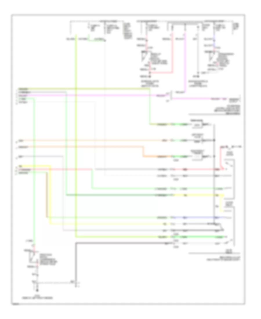
Anti-lock Brakes Wiring Diagram (1 of 2) for Acura SLX 1996
 https://portal-diagnostov.com/license.html
Automotive Electricians Portal FZCO
Automotive Electricians Portal FZCO
https://portal-diagnostov.com/license.html
https://portal-diagnostov.com/license.html
Automotive Electricians Portal FZCO
Automotive Electricians Portal FZCO
List of elements for Anti-lock Brakes Wiring Diagram (1 of 2) for Acura SLX 1996:
- (w/o cruise)
- 4wd indicator light
- 4wd switch in
- Abs ind. ctrl
- Abs indicator light
- Braided
- Brake switch (behind dash, on brake pedal support)
- Brake switch in
- Brk. input
- C606
- C607
- Cruise control unit (top of right kick panel) (w/ cruise)
- Dash fuse box
- Data link connector (left side of dash, above hood
- Dlc in/out
- Electronic brake control module (ebcm) (behind center of dash, below radio)
- Engine controls system (powertrain control module)
- Exterior lights system (brake lights)
- Fuse c-10 meter gauge 10a
- Fuse c-14 stop a/t cont 15a
- Fuse c-4 elec. ign 10a
- G sensor- abs (below center console, rear of park brake lever)
- G sensor-abs in
- G104 (rear of left front fender)
- G302 (right side of front console)
- Gauge assembly
- Ground
- Hot at all times
- Hot in on or start
- Ignition
- Left front abs speed sensor (inside of left front wheel)
- Left rear abs speed sensor (inside of left rear wheel)
- Lever)
- Lf valve ctrl
- Motor relay ctrl
- Pump motor on in
- Rear valve ctrl
- Red
- Release
- Reverse/low in
- Rf valve ctrl
- Right front abs speed sensor (inside of right front wheel)
- Right rear abs speed sensor (inside of right rear wheel)
- Valve relay ctrl
- Valve relay in
- Wheel speed in-hi
- Wheel speed in-lo
Anti-lock Brakes Wiring Diagram (2 of 2) for Acura SLX 1996
List of elements for Anti-lock Brakes Wiring Diagram (2 of 2) for Acura SLX 1996:
- 1&2
- A/t
- A12
- Abs hydraulic unit (right front of engine compt.)
- Back-up light switch (top left side side of trans.)
- C182
- C189
- C328
- C329
- Dash fuse box
- Diode box
- Engine controls system (upshift relay-2)
- Exterior lights system (back-up lights)
- Front axle switch (underside of vehicle, center of front axle)
- Fuse c-3 turn back 15a
- Fuse c-4 elec. ign 10a
- Fuse f-9 abs 20a
- Fuse fl-6 abs 4/wheel only 40a
- Fuse/ relay box (right side of engine compt.)
- G104 (rear of left front fender)
- Hot at all times
- Hot in on or start
- Left front valve
- Motor relay
- Powertrain control module (pcm) (behind center of dash, below radio)
- Pump motor
- Rear valve
- Red
- Reverse output
- Right front valve
- Transmission switch 1st/2nd (top left front of trans.)
- Valve relay

 Čeština
 Dansk
Dansk Deutsch
 Ελληνικά
 English
 English
 Español
 Suomi
Suomi Français
 עברית
עברית Hrvatski
 Magyar
 Italiano
 日本語
日本語 한국어
한국어 Nederlands
 Polski
 Português
 Português
 Română
 Русский
 Slovenčina
 Slovenščina
 Svenska
 Türkçe
 中文 (中国)