ANTI-LOCK BRAKES
Anti-lock Brakes Wiring Diagram for Acura ZDX 2012
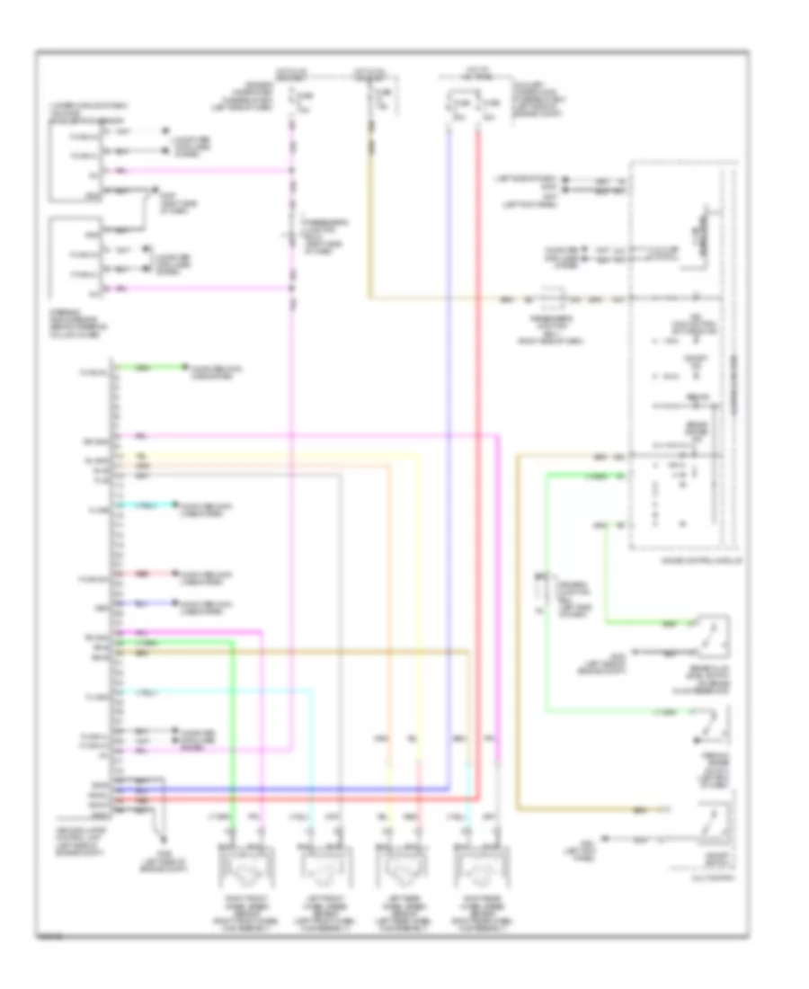
List of elements for Anti-lock Brakes Wiring Diagram for Acura ZDX 2012:
- (left side of dash) g402
- (under middle of dash) yaw rate acceleration sensor
- +b mot
- +b sol
- A13
- A14
- A15
- A17
- A26
- Abs ind
- Auxiliary under-hood fuse/relay box (left side of engine compt)
- Brake fluid level switch (on brake fluid reservoir)
- Brake system ind
- Computer data lines system
- Control circuits
- Driver's junction box (left side of dash)
- Driver's under-dash fuse/relay box (left side of dash)
- E10
- F-can a h
- F-can a l
- F-can b h
- F-can b l
- F-can transceiver
- Fl+b
- Fl-gnd
- Fr+b
- Fr-gnd
- Fuse 20a
- Fuse 40a
- Fuse 7.5a
- G302 (left side of engine compt)
- G303 (left side of engine compt)
- G401 (left kick panel)
- G405 (right side of dash)
- Gauge control module
- Gnd
- Gnd1
- Gnd2
- Hot at all times
- Hot in on or start
- Ig1
- K-line
- Left front wheel speed sensor (left front wheel hub assembly)
- Left rear wheel speed sensor (left rear wheel hub assembly)
- Multi switch
- P20
- Parking brake switch (left end of dash)
- Passenger's junction box 1 (right side of dash)
- Passenger's junction box 2 (right side of dash)
- Red
- Right front wheel speed sensor (right front wheel hub assembly)
- Right rear wheel speed sensor (right rear wheel hub assembly)
- Rl+b
- Rl-gnd
- Rr+b
- Rr-gnd
- Steering angle sensor (behind steering column cover)
- Vsa malfunction/ activation ind
- Vsa modulator control unit (left side of engine compt)
- Vsa off ind
- Vsa off switch
- Wen
 Čeština
 Dansk
Dansk Deutsch
 Ελληνικά
 English
 Español
 Suomi
Suomi Français
 Français
 עברית
עברית Hrvatski
 Magyar
 Italiano
 日本語
日本語 한국어
한국어 Nederlands
 Polski
 Português
 Português
 Română
 Русский
 Slovenčina
 Slovenščina
 Svenska
 Türkçe
 中文 (中国)
 English