ANTI-LOCK BRAKES
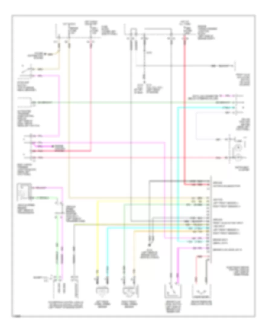
Anti-lock Brake Wiring Diagrams, New Style with Traction Control for Chevrolet Tahoe 2000
 https://portal-diagnostov.com/license.html
Automotive Electricians Portal FZCO
Automotive Electricians Portal FZCO
https://portal-diagnostov.com/license.html
https://portal-diagnostov.com/license.html
Automotive Electricians Portal FZCO
Automotive Electricians Portal FZCO
List of elements for Anti-lock Brake Wiring Diagrams, New Style with Traction Control for Chevrolet Tahoe 2000:
- A4 c1
- Abs fuse 60a
- Abs ind
- Body wiring harness junction block (near left kick panel)
- Brake fluid level sw in
- Brake fluid level switch (left side of brake fluid reservoir)
- Brake fuse 10a
- Brake in
- Brake ind
- Brake input
- Brake pressure modulator valve
- C8 a
- Data link connector (below steering column)
- Del torque
- Delivered torque
- Electronic brake control module (left side of inner frame)
- Engine wiring harness junction block (left side of engine compt)
- F6 c3
- F7 c2
- Fuse block (lower left side of dash)
- G102 (on left front body mount)
- G114 (left rear of engine)
- G200 (upper left kick panel)
- Ground
- Ground distribution system
- Hot at all times
- Hot in run
- Hot in run or start
- Ign 1 fuse 10a
- Ignition
- Instrument cluster
- Interior lights system
- Lamp active ctrl
- Lamp disable
- Left front sensor (+)
- Left front sensor (-)
- Left front wheel speed sensor
- Logic
- Low traction indicator
- Motor & solenoid pwr
- Nca
- Pnk
- Power distribution system
- Powertrain control module (left front of engine compt)
- Pump motor
- Red
- Req torque
- Requested torque
- Right front sensor (+)
- Right front sensor (-)
- Right front wheel speed sensor
- S102
- S202
- Serial data
- Sp203
- Splice pack (behind head- lamp switch)
- Stoplight switch (top of brake pedal bracket)
- Tan
- Trac sw input
- Traction assist switch
- Traction off indicator
- Vehicle speed sensor (left side of transmission/ transfer case)
- Vss high
- Vss input
- Vss low
- Vss out
Anti-lock Brake Wiring Diagrams, New Style without Traction Control for Chevrolet Tahoe 2000
List of elements for Anti-lock Brake Wiring Diagrams, New Style without Traction Control for Chevrolet Tahoe 2000:
- 4.3l
- A4 c1
- Abs fuse 60a
- Automated transfer case control module (left side of dash, above headlight switch)
- Body wiring harness junction block (near left kick panel)
- Brake fluid level sw in
- Brake fluid level switch (left side of brake fluid reservoir)
- Brake fuse 10a
- Brake input
- Brake pressure modulator valve
- C11
- C8 a
- Data link connector (below steering column)
- Electronic brake control module (left side of inner frame)
- Engine control system
- Engine wiring harness junction block (left side of engine compt)
- Except 4.3 l
- F6 c3
- F7 c2
- Front axle act/sw input
- Front axle actuator/ switch (on axle housing)
- Fuse block (lower left side of dash)
- G110 (4.8l, 5.3l, 6.0l) (left front of engine)
- G116 (left rear of engine compt, near bulkhead)
- G119 (4.3l) (rt frt of eng)
- Ground
- Hot at all times
- Hot in run
- Hot in run and start
- Ign 1 fuse 10a
- Ignition
- Instrument cluster
- Left front sensor (+)
- Left front sensor (-)
- Left front wheel speed sensor
- Logic
- Motor & solenoid pwr
- Nca
- Pnk
- Power distribution system
- Powertrain control module or vehicle control module (left front of engine compt)
- Pump motor
- Red
- Right front sensor (+)
- Right front sensor (-)
- Right front wheel speed sensor
- S102
- Serial data
- Splice pack 205 center (near left kick panel)
- Stoplamp switch (top of brake pedal bracket)
- Tan
- Vehicle speed sensor (left rear of transmission)
- Vehicle speed sensor adapter (4wd only) (left side of transfer case)
- Vss high
- Vss input
- Vss low
- Vss output
Anti-lock Brake Wiring Diagrams, Old Style for Chevrolet Tahoe 2000
List of elements for Anti-lock Brake Wiring Diagrams, Old Style for Chevrolet Tahoe 2000:
- (engine harn, near ebcm breakout) s111
- (selectable 4wd harn, near breakout to transfer case relay)
- 4wd sw input
- Abs fuse 60a
- Abs ind
- Abs ind ground
- Battery
- Brake fuse 18 10a
- Brake ind
- Brake ind input
- Brake lamp ind out
- Brake pressure warning switch (underside of ebcm)
- Brake sw input
- Brake sw output
- Data link connector (dlc) (left of steering column)
- Daytime running lamp (drl) module (behind left side of dash)
- Ebcm ground
- Electronic brake control module (left side of engine compt)
- Electronic variable orifice (evo)/ passlock control module (under center of dash)
- Engine controls system
- Front axle actuator (on right rear of front drive axle)
- Fuse/relay block (left rear of engine compt)
- G119 (right front of eng block)
- Gauges fuse 4 10a
- Hot at all times
- Hot in run
- Hot in run or start
- I/p fuse block (under left side of dash)
- Ignition
- Instrument cluster
- Left front wheel speed sensor
- M/t
- Pnk
- Pump motor ground
- Red
- Right front wheel speed sensor
- S107
- S147
- S150 (engine harn, approx 13 cm from ebcm breakout)
- S151
- S152
- S213
- S280 (i/p harn, approx 5 cm from dlc breakout)
- S314
- Sensor high
- Sensor low
- Serial data
- Serial data line
- Stoplamp switch (top of brake pedal)
- Tan
- Transfer case control module (on steering column support bracket)
- Transmissions system
- Vehicle control module (vcm) (left side of engine compt)
- Vehicle speed sensor (vss) (left side of transmission/ transfer case)
- Vehicle speed sig
- Vss (+)
- Vss (-)
- Vss sig

 Čeština
 Dansk
Dansk Deutsch
 Ελληνικά
 English
 Español
 Suomi
Suomi Français
 Français
 עברית
עברית Hrvatski
 Magyar
 Italiano
 日本語
日本語 한국어
한국어 Nederlands
 Polski
 Português
 Português
 Română
 Русский
 Slovenčina
 Slovenščina
 Svenska
 Türkçe
 中文 (中国)