ANTI-LOCK BRAKES
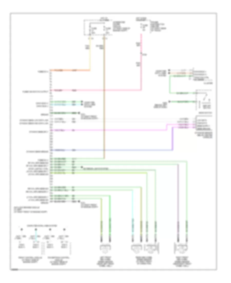
Anti-lock Brakes Wiring Diagram for Dodge Magnum SRT-8 2007
List of elements for Anti-lock Brakes Wiring Diagram for Dodge Magnum SRT-8 2007:
- 30a
- 50a
- A107
- A111
- Antilock brakes module (w/ esp) (at right front of engine compt)
- B221
- Bank switch
- Can b bus (+)
- Can b bus (-)
- Can c bus (+)
- Can c bus (-)
- Cluster
- Computer data lines system
- D51
- D52
- D64
- D65
- Dynamic sens ground
- Dynamic sens high data link
- Dynamic sens low data link
- Dynamic sens sply
- Dynamics sensor (below center console)
- Esp off switch
- Exterior lights system
- F202
- Front control module (at right side of engine compt)
- Fuse
- Fused b (+)
- Fused ign switch output
- G101 (at right front of engine compt)
- G200 (behind left side of dash)
- G94
- Ground
- High data
- Hot at all times
- Hot in run or start
- Integrated power module (at right side of engine compt)
- Left front abs wheel speed sensor (near left front wheel well)
- Lf whl spd sens sig
- Lf whl spd sens sply
- Low data
- Lr whl spd sens sig
- Lr whl spd sens sply
- Nca
- Power distribution center (at right rear of trunk)
- Powertrain control module (at right rear of engine compt)
- Rear abs wheel speed sensor (at right front of cargo pan)
- Rf whl spd sens sig
- Rf whl spd sens sply
- Right front abs wheel speed sensor (near right front wheel well)
- Rr whl spd sens sig
- Rr whl spd sens sply
- S126
- Sens ground
- Stop lamp rly ctrl
- Tan/ red
- Tan/red
- Traction ctrl sw sense
- Z903
 Čeština
 Dansk
Dansk Deutsch
 Ελληνικά
 English
 English
 Español
 Suomi
Suomi Français
 Français
 עברית
עברית Hrvatski
 Magyar
 Italiano
 日本語
日本語 한국어
한국어 Nederlands
 Polski
 Português
 Português
 Română
 Русский
 Slovenščina
 Svenska
 Türkçe
 中文 (中国)
 Slovenčina