ANTI-LOCK BRAKES
Anti-lock Brake Wiring Diagrams for Ford Crown Victoria LX 2001
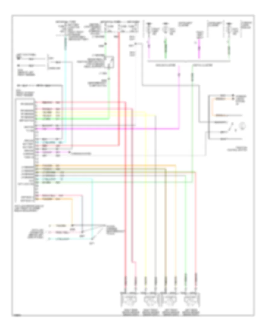
List of elements for Anti-lock Brake Wiring Diagrams for Ford Crown Victoria LX 2001:
- (in main harness, near breakout to dlc)
- (left kick panel) g200
- Analog cluster
- Anti- lock ind
- Anti-lock brake module (left front of upper radiator support)
- Anti-lock ind
- Battery
- Battery junction box (right front of engine compartment, behind battery)
- Bpp switch
- Brake pedal position (bpp) switch (top of brake pedal support)
- Central junction box (left of steering column)
- Data link connector (behind left side of dash)
- Digital cluster
- Dlc
- Fuse 10a
- Fuse 15a
- Fuse 50a
- G101 (front of right front fender)
- G104 (rear of left front fender)
- Gasoline
- Ground
- Hot at all times
- Hot in run
- Ign
- Ignition
- Instrument cluster
- Interior lights system jr
- Left front brake sensor (brake ass'y)
- Left rear brake sensor (brake ass'y)
- Lf sensor
- Lr sensor
- Nca
- Ngv
- Red
- Red/pnk
- Rf sensor
- Right front brake sensor (brake ass'y)
- Right rear brake sensor (brake ass'y)
- Rr sensor
- S112
- S231
- S258 (near breakout to bpp switch)
- S265
- S271
- S296
- S297
- Scp bus (+)
- Scp bus (-)
- Tc ind
- Tcsw in
- Tract asst ind
- Tract asst input
- Traction control switch
- Warning
- Warning lamps module
- Warning system
 Čeština
 Dansk
Dansk Deutsch
 Ελληνικά
 English
 Español
 Suomi
Suomi Français
 Français
 עברית
עברית Hrvatski
 Magyar
 Italiano
 日本語
日本語 한국어
한국어 Nederlands
 Polski
 Português
 Português
 Română
 Русский
 Slovenčina
 Slovenščina
 Svenska
 Türkçe
 中文 (中国)
 English