ANTI-LOCK BRAKES
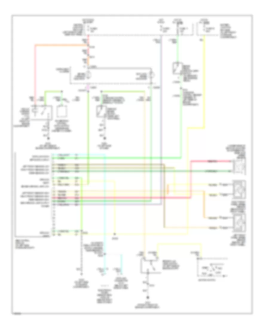
Anti-lock Brakes Wiring Diagram, without Stripped Chassis for Ford Econoline E250 2003
List of elements for Anti-lock Brakes Wiring Diagram, without Stripped Chassis for Ford Econoline E250 2003:
- (in window regulator relay
- (near brake master cylinder)
- (under rear of vehicle, mounted on differential) rear axle speed sensor
- 7.3l
- Abs control module (at left side of engine compt)
- Abs warning lamp output
- Acc
- Anti-lock brake indicator
- Battery junction box (bjb) (in left front of engine compartment)
- Bpp switch input
- Brake fluid level switch (at left side of engine compt)
- Brake pedal position (bpp) switch (on bracket, above brake pedal)
- Brake warning indicator
- Brake warning lamp low
- C220b
- C220c
- Central junction box (cjb) (left side of dash, near kick panel)
- Data link conn
- Data link connector (dlc) (below left side of dash)
- Electronic crash sensor (ecs) module (behind right side of dash)
- Fuse 1 20a
- Fuse 11 15a
- Fuse 19 60a
- Fuse 2 15a
- G100 (at left side of engine compartment)
- G101 (at right front of engine compartment)
- G203 (at left side of dash)
- Ground
- Hot at all times
- Hot in run
- Hot in run or start
- Ignition switch
- Instrument cluster
- Left front sensor high
- Left front sensor low
- Left front wheel speed sensor (behind left front wheel)
- Lock
- Nca
- Off
- Parking brake switch (near left kick panel)
- Power
- Powertrain control module (pcm)
- Rear sensor high
- Rear sensor low
- Red/pnk
- Right front sensor high
- Right front sensor low
- Right front wheel speed sensor (behind right front wheel)
- Run
- S1020
- S122
- S125 (in engine control sensor harness, in breakout to c219)
- S134 (in engine control sensor harness, at left rear of engine compartment)
- S143
- S146
- S207
- S213
- S228
- Start
- Switch harness, near breakout to c237)
- Vacuum warning switch (7.3l) (in left front of engine compartment)
- Vbatt
 Čeština
 Dansk
Dansk Deutsch
 Ελληνικά
 English
 Español
 Suomi
Suomi Français
 Français
 עברית
עברית Hrvatski
 Magyar
 Italiano
 日本語
日本語 한국어
한국어 Nederlands
 Polski
 Português
 Português
 Română
 Русский
 Slovenčina
 Slovenščina
 Svenska
 Türkçe
 中文 (中国)
 English