ANTI-LOCK BRAKES
Anti-lock Brake Wiring Diagrams for Ford Escape 2001
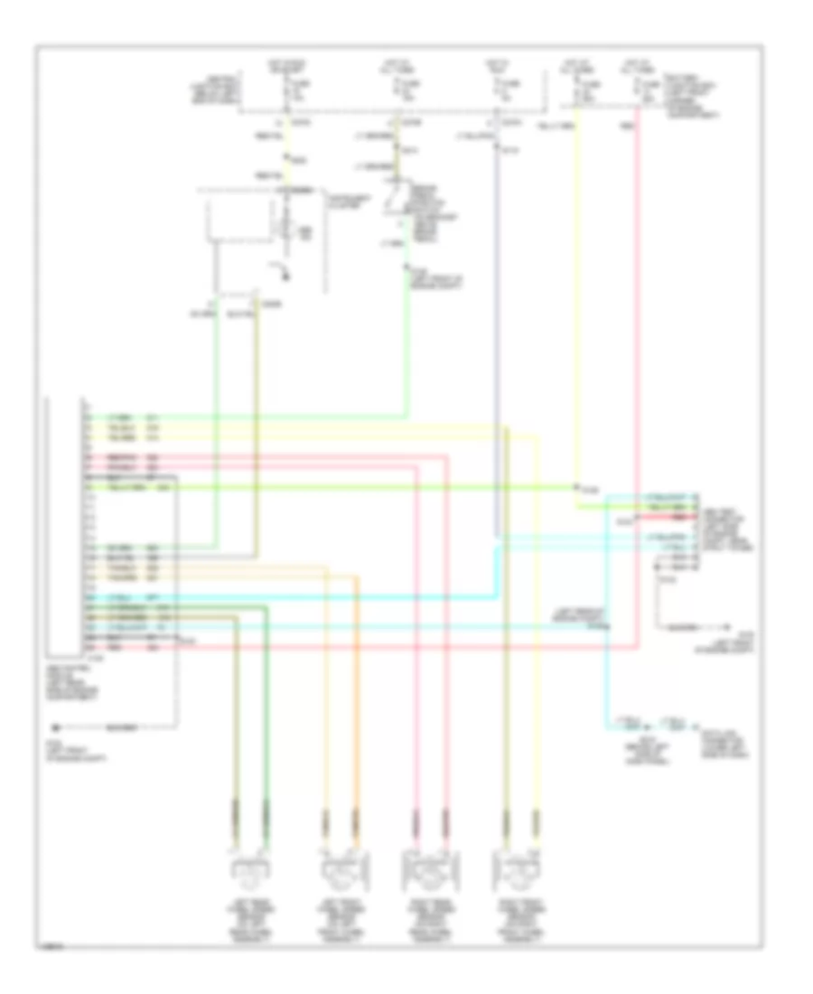
List of elements for Anti-lock Brake Wiring Diagrams for Ford Escape 2001:
- (left rear of engine compt) s125
- Abs control module (left rear side of engine compartment)
- Abs ind
- Abs test connector (left side
- Battery junction box (left front corner of engine compartment)
- Brake pedal position switch (on bracket above brake pedal)
- C135
- C220b
- C270a
- C270c
- C270e
- Central junction box (below left end of dash)
- Data link connector (lower left side of dash)
- Fuse 10a
- Fuse 15a
- Fuse 25a
- Fuse 5a
- Fuse 60a
- G100 (left front of engine compt)
- Hot at all times
- Hot in run
- Hot in run or start
- Instrument cluster
- Left front wheel speed sensor (on left front wheel assembly)
- Left rear wheel speed sensor (on left rear wheel assembly)
- Of engine compt, near strut tower)
- Red
- Red/pnk
- Right front wheel speed sensor (on right front wheel assembly)
- Right rear wheel speed sensor (on right rear wheel assembly)
- S119
- S123
- S124
- S126
- S132
- S139 (left front of engine compt)
- S219 (behind left side of dash panel)
- S222
- S314
 Čeština
 Dansk
Dansk Deutsch
 Ελληνικά
 English
 Español
 Suomi
Suomi Français
 Français
 עברית
עברית Hrvatski
 Magyar
 Italiano
 日本語
日本語 한국어
한국어 Nederlands
 Polski
 Português
 Português
 Română
 Русский
 Slovenčina
 Slovenščina
 Svenska
 Türkçe
 中文 (中国)
 English