ANTI-LOCK BRAKES
Anti-lock Brake Wiring Diagrams for Ford Expedition 1997
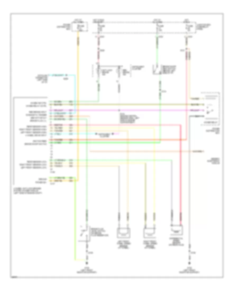
List of elements for Anti-lock Brake Wiring Diagrams for Ford Expedition 1997:
- 4 wheel anti-lock brakes system (4wabs) module (left side of engine compt)
- 4 wheel drive input
- 4wabs ind ctrl
- 4wabs relay
- 4wabs relay cctrl
- Abs active out
- Anti-lock brake ind
- Brake fluid level switch (on brake fluid reservoir)
- Brake fluid lvl
- Brake on/off (boo) switch (behind left side of i/p)
- Brake on/off switch
- C146
- C147
- C242
- C243
- Datalink connector (left side of i/p)
- Diagnostic trigger
- Differential speed sensor (on rear axle)
- Fuse 15a
- Fuse 5a
- Fuse 60a
- G108 (left front radiator support)
- Generic electronic module
- Ground
- Hot at all times
- Hot in run
- Hot in run or start
- Ignition feed
- Instrument cluster
- Junction box fuse/relay panel
- Left front sensor (high)
- Left front sensor (low)
- Left front wheel speed sensor (at wheel)
- Power (b+)
- Power distribution box
- Rear sensor (high)
- Rear sensor (low)
- Red brake ind
- Red brake input
- Red/pnk
- Right front sensor (high)
- Right front sensor (low)
- Right front wheel speed sensor (at wheel)
- S106
- S121
- S144
- S144 (engine control sensor harn, left side of engine compartment)
- S225
- S229
- Tan/red
 Čeština
 Dansk
Dansk Deutsch
 Ελληνικά
 English
 Español
 Suomi
Suomi Français
 Français
 עברית
עברית Hrvatski
 Magyar
 Italiano
 日本語
日本語 한국어
한국어 Nederlands
 Polski
 Português
 Português
 Română
 Русский
 Slovenčina
 Slovenščina
 Svenska
 Türkçe
 中文 (中国)
 English