ANTI-LOCK BRAKES
Anti-lock Brake Wiring Diagrams for Ford Mustang GT 1998
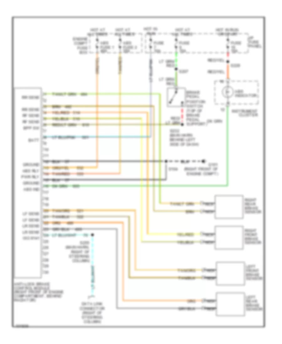
List of elements for Anti-lock Brake Wiring Diagrams for Ford Mustang GT 1998:
- Abs fuse 1 40a
- Abs fuse 2 20a
- Abs ind
- Abs indicator
- Abs rly
- All times
- All times engine compt fuse box
- Anti-lock brake control module (right front of engine compartment, behind radiator)
- Batt
- Bpp sw
- Brake pedal
- Data link connector (right of steering column)
- Fuse 10a
- Fuse 15a
- G101 (right front of engine compt)
- Ground
- Hot at
- Hot at all times
- Hot in
- Hot in run or start
- I/p fuse panel
- Instrument cluster
- Iso 9141
- Left front brake sensor
- Left rear brake sensor
- Lf sens
- Lr sens
- Nca
- Position switch (top of brake pedal support)
- Pwr rly
- Rf sens
- Right front brake sensor
- Right rear brake sensor
- Rr sens
- Run
- S104
- S207
- S229
- S232 (main harn behind left side of dash)
- S255 (main harn, right of steering column)
- Tan/red
 Čeština
 Dansk
Dansk Deutsch
 Ελληνικά
 English
 Español
 Suomi
Suomi Français
 Français
 עברית
עברית Hrvatski
 Magyar
 Italiano
 日本語
日本語 한국어
한국어 Nederlands
 Polski
 Português
 Português
 Română
 Русский
 Slovenčina
 Slovenščina
 Svenska
 Türkçe
 中文 (中国)
 English