ANTI-LOCK BRAKES
Anti-lock Brakes Wiring Diagram for Ford Transit Connect Electric 2012
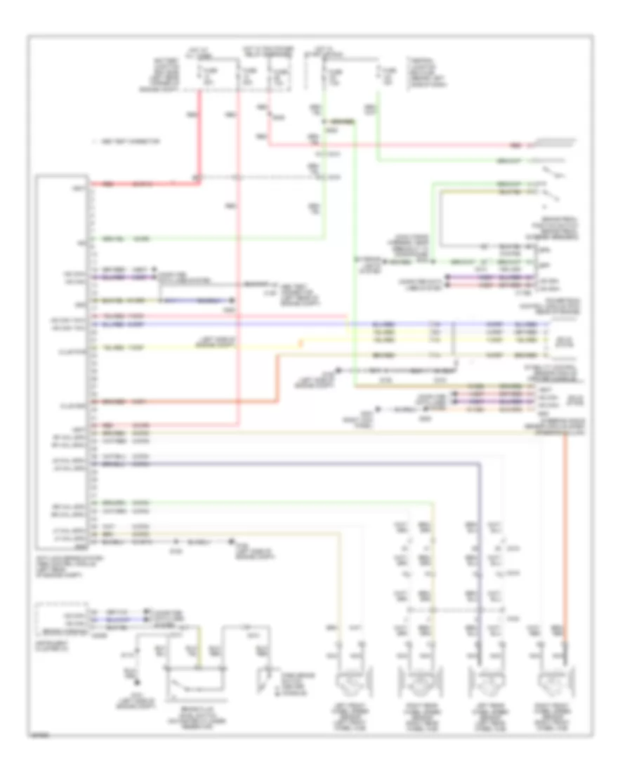
List of elements for Anti-lock Brakes Wiring Diagram for Ford Transit Connect Electric 2012:
- (left rear of engine compt)
- (left side of engine compt)
- (main wiring harness, near breakout to microphone) s234
- 15-ce8
- 15-cf6
- 15s-lg23
- 30-cf13
- 30-cf6
- 4-cf67
- 4-ec7
- 5-cf67
- 5-ec7
- 7-cf67
- 8-cf32
- 8-cf34
- 8-cf38
- 8-cf40
- 9-cf1
- 9-cf32
- 9-cf34
- 9-cf38
- 9-cf40
- 9-cf67
- 91-ce8
- 91-cf13
- 91-cf6
- 91s-pg6
- Abs test connector
- Abs test connector c126
- Anti-lock brake system (abs) control module (left rear of engine compt)
- Battery junction box (bjb) (left rear corner of engine compt)
- Bpp
- Bps
- Brake fluid level switch (on master cylinder reservoir)
- Brake pedal position switch (brake pedal support bracket)
- Brake warning
- C175b
- C213
- C215
- C216
- C219
- C220b
- C432
- Central junction box (cjb) (behind left side of dash)
- Clus gnd
- Clus pwr
- Computer data lines system
- Exterior lights system
- Fuse 10a
- Fuse 15a
- Fuse 20a
- Fuse 30a
- Fuse 7.5a
- G101 (left side of engine compt)
- G102
- G106 (left side of engine compt)
- G203 (right kick panel)
- Gnd
- Hot at all times
- Hot in start or run
- Hot w/ pcm power relay energized
- Hs can yaw+
- Hs can yaw-
- Hs can+
- Hs can-
- Ign
- Instrument cluster (ic)
- Left front wheel speed sensor (left front wheel hub)
- Left rear wheel speed sensor (left rear wheel hub)
- Lf whl spd+
- Lf whl spd-
- Lr whl spd+
- Lr whl spd-
- Nca
- Park brake switch (center console)
- Powertrain control module (pcm) (rear of engine)
- Red
- Rf whl spd+
- Rf whl spd-
- Right front wheel speed sensor (right front wheel hub)
- Right rear wheel speed sensor (right rear wheel hub)
- Rr whl spd+
- Rr whl spd-
- S111
- S115
- S152
- S220
- S236
- S280
- Solid state
- Stability control sensor module (center console)
- Steering angle sensor module (sasm) (steering column)
- Vbat
 Čeština
 Dansk
Dansk Deutsch
 Ελληνικά
 English
 Español
 Suomi
Suomi Français
 Français
 עברית
עברית Hrvatski
 Magyar
 Italiano
 日本語
日本語 한국어
한국어 Nederlands
 Polski
 Português
 Português
 Română
 Русский
 Slovenčina
 Slovenščina
 Svenska
 Türkçe
 中文 (中国)
 English