ANTI-LOCK BRAKES
Anti-lock Brake Wiring Diagrams for GMC Safari 1999
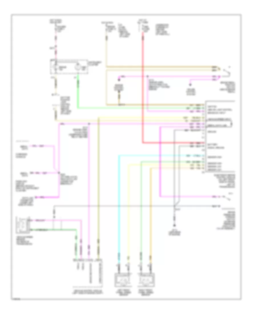
List of elements for Anti-lock Brake Wiring Diagrams for GMC Safari 1999:
- Abs fuse 60a
- Abs ind
- Abs ind lamp control
- B17
- Battery
- Brake fuse 18 10a
- Brake ind
- Brake pedal position switch (above brake pedal)
- Brake pressure warning switch (on brake pressure modulator valve assembly
- Brake sw input
- Brake sw output
- Cruise control system
- Data link connector (under left side of dash)
- Daytime running lamp control module (behind left side of dash)
- Electronic brake control module (on left front side of frame, left of transmission)
- Engine control system
- G114 (lefr rear of engine)
- Gauges fuse 4 10a
- Ground
- Hot at all times
- Hot in run
- Hot in run and start
- I/p fuse block (behind left side of dash)
- Ignition
- Instrument cluster
- Left front wheel speed sensor
- Nca
- Overhead console
- Passlock module (behind air duct, right of instrument cluster)
- Pnk
- Red
- Right front wheel speed sensor
- S112 (engine harn, 48.5 cm from c100 breakout toward engine)
- S113 (engine harn, 10.5 cm from underhood fuse/ relay center)
- S114
- S127
- S213
- S233 (i/p harn, 6.5 cm from data link connector breakout)
- Sensor high
- Sensor low
- Serial data
- Serial data line
- Signal ground
- Tan
- Underhood fuse/relay center (left side of firewall)
- Vehicle control module (left side of engine compt)
- Vehicle speed input
- Vehicle speed sensor (on rear of transmission)
- Vehicle speed sig
- Vss (+)
- Vss (-)
 Čeština
 Dansk
Dansk Deutsch
 Ελληνικά
 English
 Español
 Suomi
Suomi Français
 Français
 עברית
עברית Hrvatski
 Magyar
 Italiano
 日本語
日本語 한국어
한국어 Nederlands
 Polski
 Português
 Português
 Română
 Русский
 Slovenčina
 Slovenščina
 Svenska
 Türkçe
 中文 (中国)
 English