ANTI-LOCK BRAKES
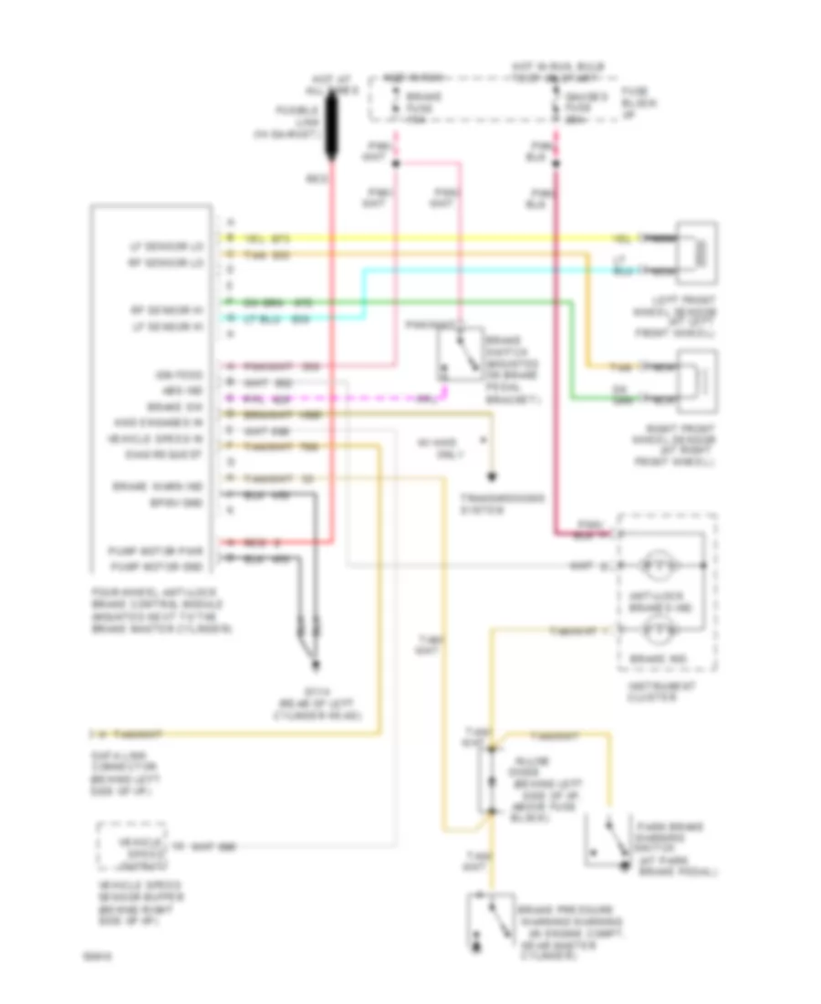
All-Wheel ABS Wiring Diagram, with Brake Control Module, with DRL for GMC Sonoma 1994
 https://portal-diagnostov.com/license.html
Automotive Electricians Portal FZCO
Automotive Electricians Portal FZCO
https://portal-diagnostov.com/license.html
https://portal-diagnostov.com/license.html
Automotive Electricians Portal FZCO
Automotive Electricians Portal FZCO
List of elements for All-Wheel ABS Wiring Diagram, with Brake Control Module, with DRL for GMC Sonoma 1994:
- (at left
- (at park
- (at right
- (behind left side of i/p)
- (behind left side of i/p, above fuse
- 4wd engaged in
- Abs ind
- Anti-lock brakes ind.
- Block)
- Bpmv gnd
- Brake fuse 15a
- Brake ind.
- Brake pedal)
- Brake pressure warning warning (in engine compt, near master cylinder)
- Brake sw
- Brake switch (mounted on brake pedal bracket)
- Brake warn ind
- Cluster
- Data link connector (behind left side of i/p)
- Diag request
- Diode module
- Drl module
- Four-wheel anti-lock brake control module (mounted next to the brake master cylinder)
- Front wheel)
- Fuse block: i/p
- Fusible link (14 ga-rust)
- G114 (rear of left cylinder head)
- Gauges fuse 20a
- Hot at all times
- Hot in run
- Hot in run, bulb test or start
- Ign feed
- Ignition switch
- Instrument
- Left front wheel sensor
- Lf sensor hi
- Lf sensor lo
- Nca
- Only
- Output
- Park brake
- Pnk/
- Pnk/ h
- Pump motor gnd
- Pump motor pwr
- Red
- Rf sensor hi
- Rf sensor lo
- Right front wheel sensor
- Speed
- Switch
- Tan
- Tan/ a
- Transmissions system
- Vehicle
- Vehicle speed in
- Vehicle speed sensor buffer (behind right side of i/p)
- W/ 4wd
- Warning
All-Wheel ABS Wiring Diagram, with Brake Control Module, without DRL for GMC Sonoma 1994
List of elements for All-Wheel ABS Wiring Diagram, with Brake Control Module, without DRL for GMC Sonoma 1994:
- (at left
- (at park
- (at right
- (behind left side of i/p, above fuse
- 4wd engaged in
- Abs ind
- Anti-lock brakes ind.
- Block)
- Bpmv gnd
- Brake fuse 15a
- Brake ind.
- Brake pedal)
- Brake pressure
- Brake sw
- Brake switch (mounted on brake pedal bracket)
- Brake warn ind
- Cluster
- Cylinder)
- Data link connector (behind left side of i/p)
- Diag request
- Diode
- Four-wheel anti-lock brake control module (mounted next to the brake master cylinder)
- Front wheel)
- Fuse block: i/p
- Fusible link (14 ga-rust)
- G114 (rear of left cylinder head)
- Gauges fuse 20a
- Hot at all times
- Hot in run
- Hot in run, bulb test or start
- Ign feed
- In-line
- Instrument
- Left front wheel sensor
- Lf sensor hi
- Lf sensor lo
- Nca
- Near master
- Only
- Output
- Park brake
- Pnk/
- Pnk/ h
- Pump motor gnd
- Pump motor pwr
- Red
- Rf sensor hi
- Rf sensor lo
- Right front wheel sensor
- Speed
- Switch
- Tan
- Transmissions system
- Vehicle
- Vehicle speed in
- Vehicle speed sensor buffer (behind right side of i/p)
- W/ 4wd
- Warning
- Warning warning (in engine compt,
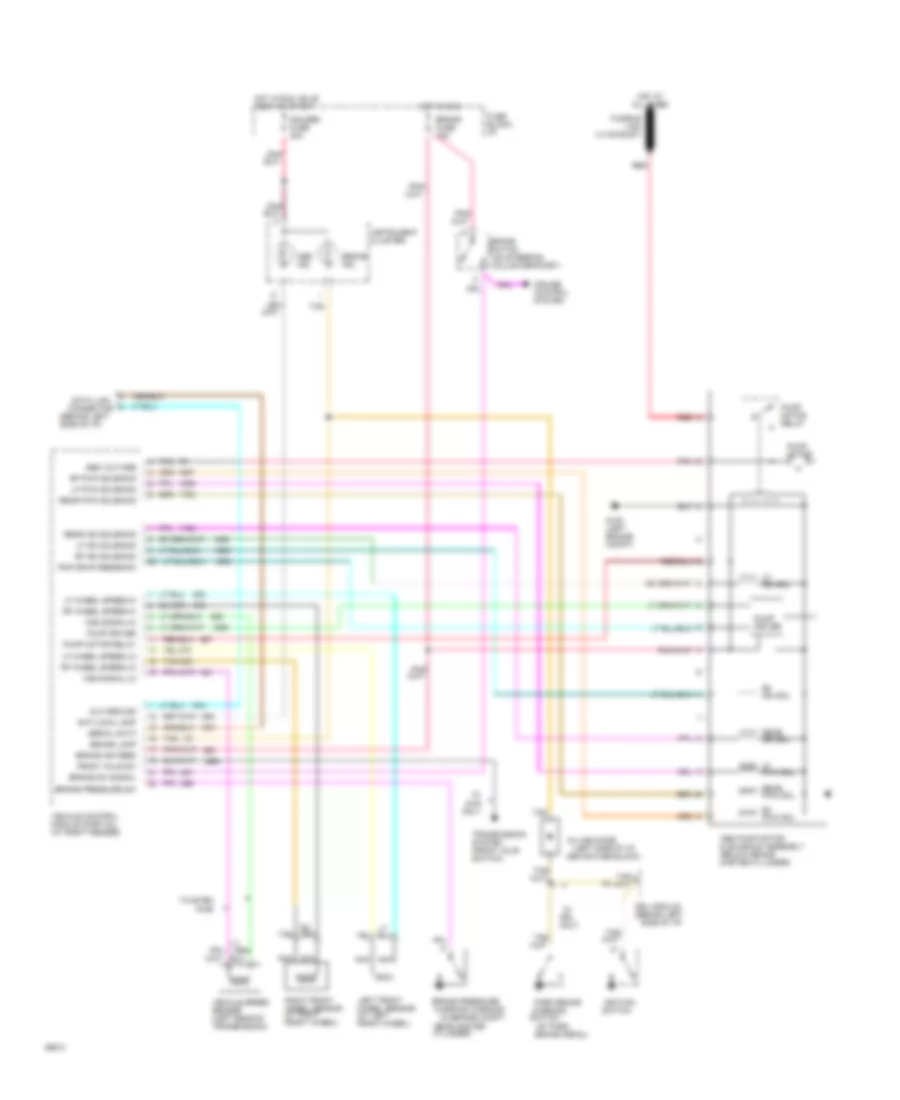
All-Wheel ABS Wiring Diagram, with Vehicle Control Module for GMC Sonoma 1994
List of elements for All-Wheel ABS Wiring Diagram, with Vehicle Control Module for GMC Sonoma 1994:
- (at left front wheel)
- (at park
- (at right front wheel)
- (behind left side of i/p)
- (left side of i/p,
- (on steering column bracket)
- Above fuse block)
- Abs ind.
- Abs pump motor & solenoid assembly (below brake master cylinder)
- Abs voltage
- Anti-lock lamp
- Brake fuse 15a
- Brake ign feed
- Brake ind.
- Brake lamp
- Brake pedal)
- Brake pressure
- Brake pressure sw
- Brake sw signal
- Brake switch
- Connector
- Cruise control system
- Cylinder)
- Data link
- Dlc ground
- Drl module
- Front axle sw
- Fuse block: i/p
- Fusible link (14 ga-rust)
- G102 (left engine compt)
- Gauges fuse 20a
- Hot at all times
- Hot in run
- Hot in run, bulb test or start
- Ignition switch
- In-line diode
- Instrument cluster
- Left front
- Lf iso sol
- Lf iso solenoid
- Lf pwm sol
- Lf pwm solenoid
- Lf wheel speed-hi
- Lf wheel speed-lo
- Nca
- Near master
- Only
- Park brake
- Pmp drvr feedback
- Pnk
- Pnk/
- Pump driver
- Pump motor
- Pump motor relay
- Rear iso sol
- Rear iso solenoid
- Rear pwm sol
- Rear pwm solenoid
- Red
- Rf iso sol
- Rf iso solenoid
- Rf pwm sol
- Rf pwm solenoid
- Rf wheel speed-hi
- Rf wheel speed-lo
- Right front
- Serial data
- Switch
- Tan
- Tan/ a
- Transmission system (front axle switch)
- Twisted pair
- Vehicle control module (partial) (at right fender)
- Vehicle speed sensor (left rear of transmission)
- Vss signal-hi
- Vss signal-lo
- W/ 4wd only
- W/ drl
- Warning
- Warning warning (in engine compt,
- Wheel sensor
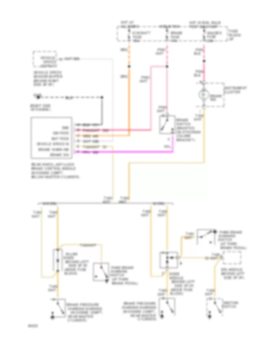
Rear Wheel ABS Wiring Diagram for GMC Sonoma 1994
List of elements for Rear Wheel ABS Wiring Diagram for GMC Sonoma 1994:
- (at park
- (behind left side of i/p)
- (behind left side of i/p, above fuse
- (right side of engine)
- All times
- Bat feed
- Block)
- Brake fuse 15a
- Brake ind.
- Brake pedal)
- Brake pressure
- Brake pressure warning warning (in engine compt, near master cylinder)
- Brake sw
- Brake switch (mounted on steering column bracket)
- Brake warn ind
- Cluster
- Cylinder)
- Diode
- Drl module
- Ecm batt fuse 15a
- Fuse block: i/p
- G120
- Gauges fuse 20a
- Gnd
- Hot at
- Hot in run
- Hot in run, bulb test or start
- Ign feed
- Ignition switch
- In-line
- Instrument
- Module
- Near master
- Output
- Park brake
- Pnk/
- Rear wheel anti-lock brake control module (in engine compt, below master cylinder)
- Speed
- Switch
- Tan/ a
- Vehicle
- Vehicle speed in
- Vehicle speed sensor buffer (behind right side of i/p)
- W/ drl
- W/o drl
- Warning
- Warning warning (in engine compt,

 Čeština
 Dansk
Dansk Deutsch
 Ελληνικά
 English
 Español
 Suomi
Suomi Français
 Français
 עברית
עברית Hrvatski
 Magyar
 Italiano
 日本語
日本語 한국어
한국어 Nederlands
 Polski
 Português
 Português
 Română
 Русский
 Slovenčina
 Slovenščina
 Svenska
 Türkçe
 中文 (中国)