ANTI-LOCK BRAKES
Anti-lock Brakes Wiring Diagram for GMC Sonoma 2004
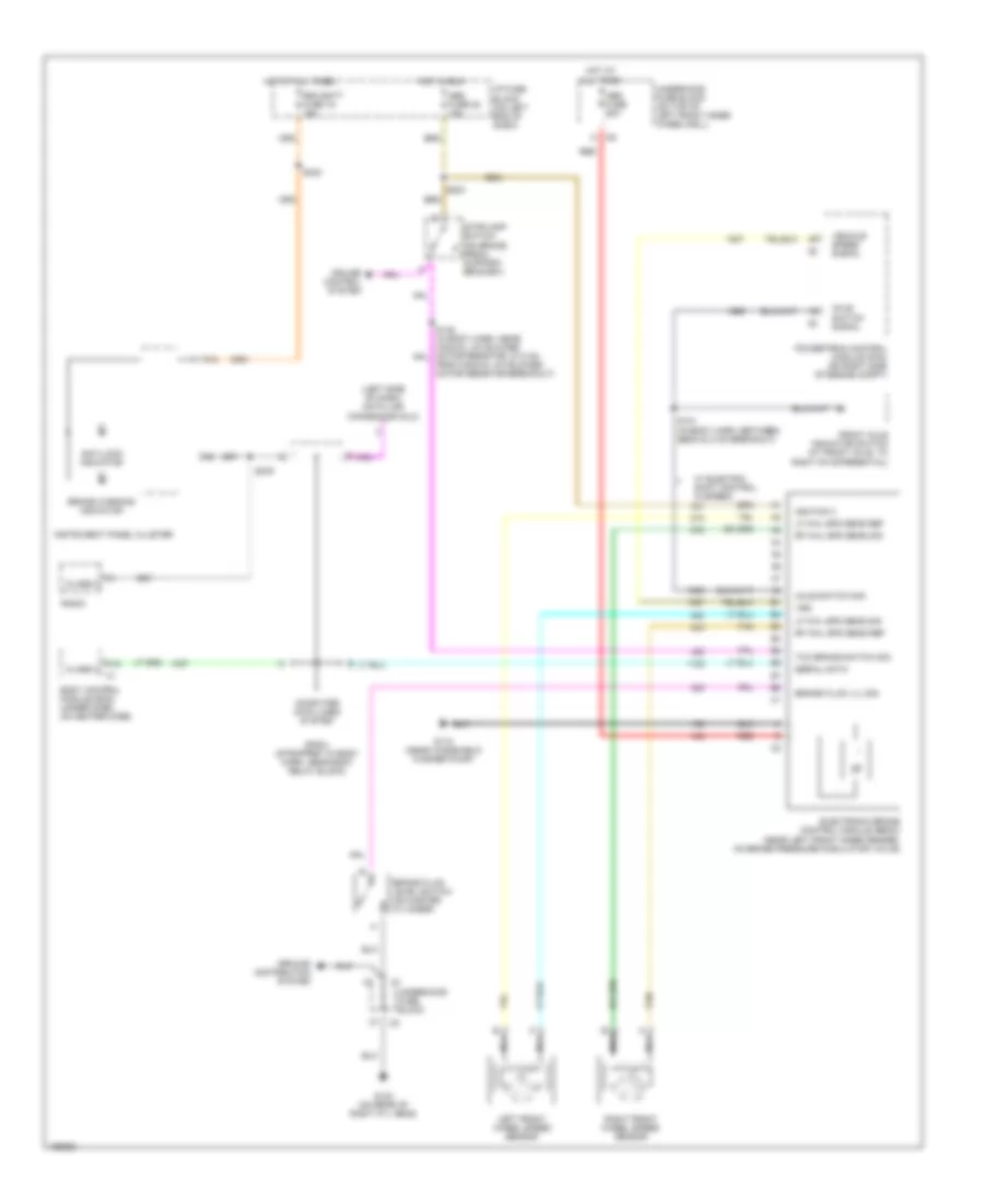
List of elements for Anti-lock Brakes Wiring Diagram for GMC Sonoma 2004:
- (left side of dash) data link connector (dlc)
- A10
- A12
- Abs fuse 22 10a
- Abs fuse 60a
- Anti-lock indicator
- Axle switch sig
- Axle switch signal
- Body control module (bcm) (under dash, on heater case)
- Brake fluid level switch (on master cylinder)
- Brake fluid lvl sig
- Brake warning indicator
- Class 2
- Computer data lines system
- Cruise control system
- Electronic brake control module (ebcm) (near left front inner fender, on brake pressure modulator valve)
- From manual a/c blower motor resistor breakout)
- Front axle indicator switch (at front axle, to right of differential)
- G102 (on rear of right cyl head)
- G110 (near windshield washer pump)
- Ground distribution system
- Hot at all times
- Hot in run
- I/p fuse block (on left end of dash)
- Ignition 3
- Instrument panel cluster
- Left front wheel speed sensor
- Lf whl spd sens ref
- Lf whl spd sens sig
- Nca
- Powertrain control module (pcm) (on right side of engine compt)
- Radio
- Rdo batt fuse 19 15a
- Red
- Rf whl spd sens ref
- Rf whl spd sens sig
- Right front wheel speed sensor
- S121 (in body harn, between ebcm & c102 breakout)
- S203
- S240
- S276
- Serial data
- Sp201 (strapped to body harn, near body relay block)
- Stoplamp switch (on brake pedal support bracket)
- Tan
- Tcc brake switch sig
- Underhood fuse block
- Underhood fuse block (on top of left front inner wheelwell)
- Vehicle speed signal
- Vss
- W/ electric shift control (2 speed)
 Čeština
 Dansk
Dansk Deutsch
 Ελληνικά
 English
 English
 Español
 Suomi
Suomi Français
 Français
 עברית
עברית Hrvatski
 Magyar
 日本語
日本語 한국어
한국어 Nederlands
 Polski
 Português
 Português
 Română
 Русский
 Slovenčina
 Slovenščina
 Svenska
 Türkçe
 中文 (中国)
 Italiano