ANTI-LOCK BRAKES
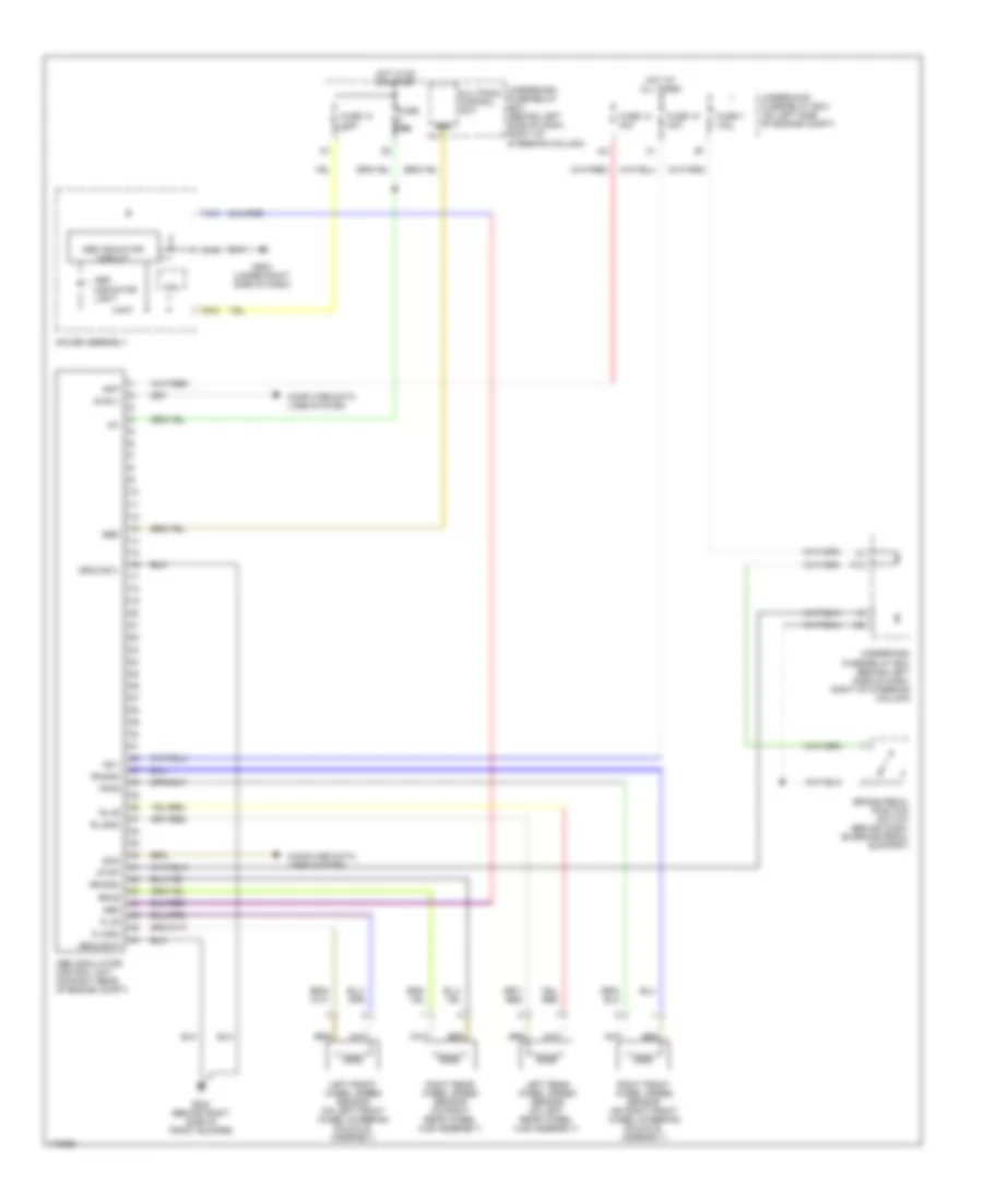
Anti-lock Brakes Wiring Diagram for Honda CR-V LX 2003
List of elements for Anti-lock Brakes Wiring Diagram for Honda CR-V LX 2003:
- +b-p
- +b-v
- A13
- A15
- Abs
- Abs indicator circuit
- Abs indicator light
- Abs modulator- control unit (on right rear of engine compt)
- B18
- Brake pedal position switch (behind dash, on brake pedal support)
- Computer data lines system
- Cpu
- Diag ii
- Ebd
- Fl+b
- Fl-gnd
- Fr+b
- Fr-gnd
- Fuse 10 30a
- Fuse 10 7.5a
- Fuse 10a
- Fuse 18 30a
- Fuse 7 15a
- G202 (behind right side of front bumper)
- G502 (under right side of dash)
- Gauge assembly
- Ground-p
- Ground-v
- Hot at all times
- Hot in on or start
- Ig1
- Left front wheel speed sensor (on left front wheel steering knuckle assembly)
- Left rear wheel speed sensor (on left rear wheel hub assembly)
- Multiplex control unit
- O12
- Right front wheel speed sensor (on right front wheel steering knuckle assembly)
- Right rear wheel speed sensor (on right rear wheel hub assembly)
- Rl+b
- Rl-gnd
- Rr+b
- Rr-gnd
- Scs
- Stop
- Underdash fuse/relay box (behind left side of dash, right of steering column)
- Underhood fuse/relay box (on left side of engine compt)
 Čeština
 Dansk
Dansk Deutsch
 Ελληνικά
 English
 Español
 Suomi
Suomi Français
 Français
 עברית
עברית Hrvatski
 Magyar
 Italiano
 日本語
日本語 한국어
한국어 Nederlands
 Polski
 Português
 Português
 Română
 Русский
 Slovenčina
 Slovenščina
 Svenska
 Türkçe
 中文 (中国)
 English