ANTI-LOCK BRAKES
Anti-lock Brakes Wiring Diagram for Honda Fit 2008
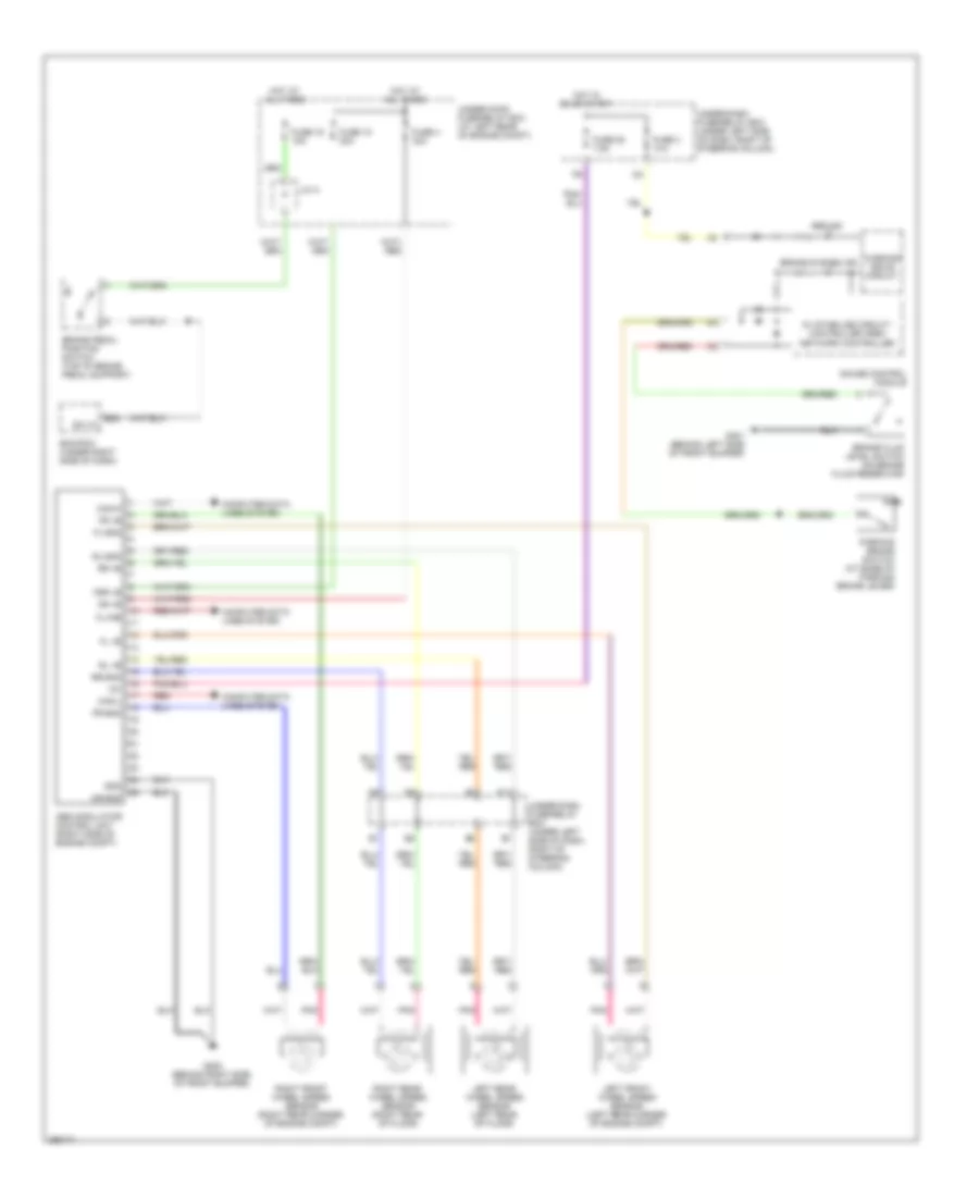
List of elements for Anti-lock Brakes Wiring Diagram for Honda Fit 2008:
- 5v stabilize circuit/ controller area network controller
- Abs ind
- Abs modulator control unit (right side of engine compt)
- Brake fluid level switch (on brake fluid reservoir)
- Brake pedal position switch (top of brake pedal support)
- Brake system ind
- Can-h
- Can-l
- Computer data lines system
- E22
- Ecm/pcm (under right side of dash)
- Fl +b
- Fl-gnd
- Fr +b
- Fr-gnd
- Fsr +b
- Fuse 15 30a
- Fuse 16 15a
- Fuse 25 7.5a
- Fuse 3 10a
- Fuse 4 30a
- G202 (behind right side of front bumper)
- G301 (behind left side of front bumper)
- Gauge control module
- Gnd
- Hot at all times
- Hot in on or start
- Ig1
- J/c a
- K-line
- Left front wheel speed sensor (left rear corner of engine compt)
- Left rear wheel speed sensor (left rear of floor)
- Mr +b
- Mr-gnd
- P11
- Parking brake switch (at base of parking brake lever)
- Pnk
- Red
- Right front wheel speed sensor (right rear corner of engine compt)
- Right rear wheel speed sensor (right rear of floor)
- Rl +b
- Rl-gnd
- Rr +b
- Rr-gnd
- Sw in
- Under-dash fuse/relay box (under left side of dash, right of steering column)
- Under-hood fuse/relay box (at left rear of engine compt)
- Warning drive circuit
 Čeština
 Dansk
Dansk Deutsch
 Ελληνικά
 English
 Español
 Suomi
Suomi Français
 Français
 עברית
עברית Hrvatski
 Magyar
 Italiano
 日本語
日本語 한국어
한국어 Nederlands
 Polski
 Português
 Português
 Română
 Русский
 Slovenčina
 Slovenščina
 Svenska
 Türkçe
 中文 (中国)
 English