ANTI-LOCK BRAKES
Anti-lock Brakes Wiring Diagram for Honda Insight 2003
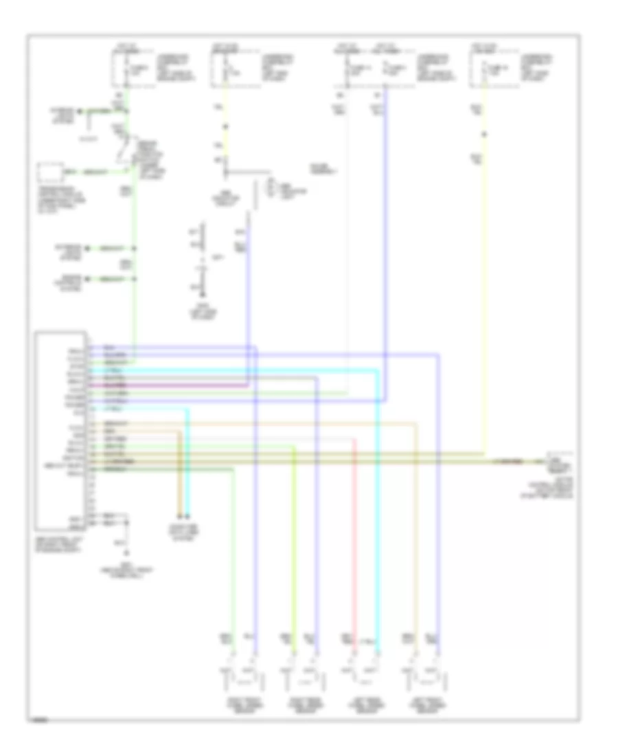
List of elements for Anti-lock Brakes Wiring Diagram for Honda Insight 2003:
- 7.5a
- A14
- Abs control unit (on right front of engine compt)
- Abs indicator circuit
- Abs indicator light
- Abs out (busy)
- Abs system (busy)
- B12
- B15
- B17
- Brake pedal position switch (under left side of dash)
- C571
- Computer data lines system
- Dlc
- Engine controls system
- Exterior lights system
- Flw(+)
- Flw(-)
- Frw(+)
- Frw(-)
- Fuse 14 20a
- Fuse 16 7.5a
- Fuse 3 30a
- Fuse 6 10a
- G201 (above right front wheelwell)
- G402 (left side of dash)
- Gauge assembly
- Gnd 1
- Gnd 2
- Hot at all times
- Hot in on or acc
- Hot in on or start
- Ignition
- Interior lights system
- Left front wheel speed sensor
- Left rear wheel speed sensor
- Motor control module (on top front of battery module
- Power
- Right front wheel speed sensor
- Right rear wheel speed sensor
- Rlw(+)
- Rlw(-)
- Rrw(+)
- Rrw(-)
- Scs
- Stop
- Transmission control module (under right side of kick panel) (w/ cvt)
- Underdash fuse/relay box (left end of dash)
- Underdash fuse/relay box (left side of dash)
- Underhood fuse/relay box (left side of engine compt)
- W/ cvt
- Walp
 Čeština
 Dansk
Dansk Deutsch
 Ελληνικά
 English
 Español
 Suomi
Suomi Français
 Français
 עברית
עברית Hrvatski
 Magyar
 Italiano
 日本語
日本語 한국어
한국어 Nederlands
 Polski
 Português
 Português
 Română
 Русский
 Slovenčina
 Slovenščina
 Svenska
 Türkçe
 中文 (中国)
 English