ANTI-LOCK BRAKES
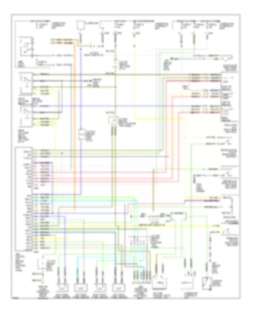
Anti-lock Brake Wiring Diagrams for Honda Prelude S 1996
List of elements for Anti-lock Brake Wiring Diagrams for Honda Prelude S 1996:
- (behind left side of i/p)
- (behind right side of i/p)
- +b1
- +b2
- +b3
- 5
- Abs control unit (behind right quarter trim panel)
- Abs ind
- Abs inspection connector (under right front seat)
- Abs pump relay
- Alternator
- Brake fluid level switch (left rear eng comp)
- Brake switch (top of brake pedal support)
- Brk ind
- C422
- C423
- C424
- C467
- C469
- C505
- C506
- Can
- Chg
- Com-
- Daytime running lights control unit
- E21
- E22
- E23
- Fl-in
- Fl-out
- Flw+
- Flw-
- Fr-in
- Fr-out
- Front fail-safe relay
- Frw+
- Frw-
- Fsr
- Fuse 13 10a
- Fuse 31 50a
- Fuse 40 15a
- Fuse 41 15a
- Fuse 48 7.5a
- Fuse 49 20a
- Fuse 9 15a
- G100 (left front fender)
- G201
- Headlamps
- Hot at all times
- Hot in on
- Hot in on or start
- Ig2
- Indicators
- Instrument cluster
- J/c c419
- J/c c419 (behind right side of i/p)
- J/c c419 (right side of i/p)
- J/c c447
- J/c c447 (behind left side of i/p)
- J/c c507 (behind right quarter trim panel)
- Left fr abs sol
- Left front wheel sensor
- Left rear wheel sensor
- Mck
- Modulator unit (right rear eng comp)
- Park
- Parking brake switch
- Pmr
- Pressure switch (right rear eng comp)
- Psw
- Pump motor (right rear eng comp)
- R-in
- R-out
- Rear abs sol
- Rear fail-safe relay (behind left side of i/p)
- Red
- Right fr abs sol
- Right front wheel sensor
- Right rear wheel sensor
- Rlw+
- Rlw-
- Rrw+
- Rrw-
- Scs
- Service check connector (behind front console)
- Stop
- Under-dash fuse/relay box
- Under-hood fuse/relay box
- Usa
- Warn 1
- Warn 2
 Čeština
 Dansk
Dansk Deutsch
 Ελληνικά
 English
 Español
 Suomi
Suomi Français
 Français
 עברית
עברית Hrvatski
 Magyar
 Italiano
 日本語
日本語 한국어
한국어 Nederlands
 Polski
 Português
 Português
 Română
 Русский
 Slovenčina
 Slovenščina
 Svenska
 Türkçe
 中文 (中国)
 English