ANTI-LOCK BRAKES
Anti-lock Brakes Wiring Diagram for Hyundai Accent 2003
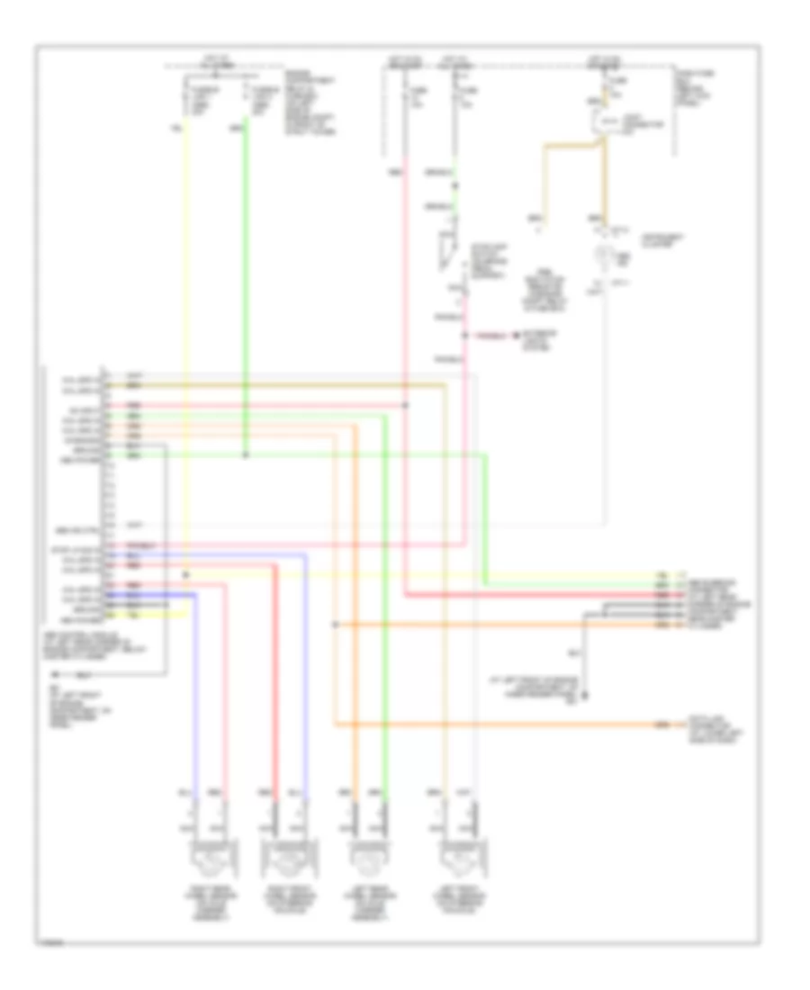
List of elements for Anti-lock Brakes Wiring Diagram for Hyundai Accent 2003:
- (at left front of engine compartment, on inner fender panel) g01
- Abs bleeding
- Abs control module (at left rear corner of engine compartment, below master cylinder)
- Abs ind
- Abs ind ctrl
- Compartment, near master cylinder)
- Connector (at left rear corner of engine
- Dash fuse box (behind left kick panel)
- Data link connector (at lower left side of dash)
- Diagnosis
- Engine compartment relay & fuse box (on left side of engine compt, in front of strut tower)
- Exterior lights system
- Fuse 10a
- Fusible link 1 (abs) 30a
- Fusible link 2 (abs) 30a
- G01 (at left front of engine compartment, on inner fender panel)
- Ground
- Hot at all times
- Hot in on or start
- Instrument cluster
- Joint connector m31
- Left front wheel sensor (on steering knuckle)
- Left rear wheel sensor (on axle carrier assembly)
- M71-1
- M71-2
- Mem power
- Nca
- On input
- Pre- excitation resistor (in engine compt relay & fuse box)
- Red
- Right front wheel sensor (on steering knuckle)
- Right rear wheel sensor (on axle carrier assembly)
- Stop lp sig in
- Stoplamp switch (on brake pedal support)
- Whl spd in
 Čeština
 Dansk
Dansk Deutsch
 Ελληνικά
 English
 Español
 Suomi
Suomi Français
 Français
 עברית
עברית Hrvatski
 Magyar
 Italiano
 日本語
日本語 한국어
한국어 Nederlands
 Polski
 Português
 Português
 Română
 Русский
 Slovenčina
 Slovenščina
 Svenska
 Türkçe
 中文 (中国)
 English