ANTI-LOCK BRAKES
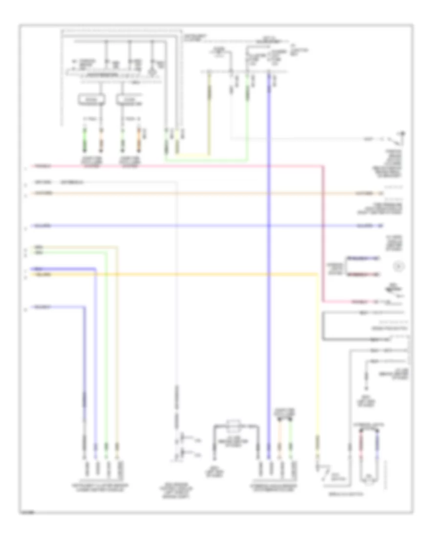
Anti-lock Brakes Wiring Diagram (1 of 2) for Hyundai Genesis 4.6 2010
 https://portal-diagnostov.com/license.html
Automotive Electricians Portal FZCO
Automotive Electricians Portal FZCO
https://portal-diagnostov.com/license.html
https://portal-diagnostov.com/license.html
Automotive Electricians Portal FZCO
Automotive Electricians Portal FZCO
List of elements for Anti-lock Brakes Wiring Diagram (1 of 2) for Hyundai Genesis 4.6 2010:
- Abs pump motor
- Auto vehicle hold sw
- Brake switch signal
- Can high
- Can low
- Computer data lines system
- E/r-e1a
- E/r-e2b
- Ecs switch
- Engine room junction box (right rear of engine compt)
- Esc control module (left front of engine compt)
- Esp fuse 10a
- Esp-1 fuse 30a
- Esp-2 fuse 30a
- Fuse & relay box (engine room) (left side of engine compt)
- Ge02 (right kick panel)
- Geo2 (right kick panel)
- Ground
- High
- Hot at all times
- Hot in on or start
- J/c jeb (left kick panel)
- K-line
- Left front wheel sensor (on left front wheel hub assembly)
- Left rear wheel sensor (left rear wheel hub assembly)
- Low
- M51-b
- Nca
- Note: esc control module contains: esc solenoids, esc pump motor
- On/start input
- Pdm (left center of dash)
- Pnk
- Power
- Red
- Right front wheel sensor (on right front wheel hub assembly)
- Right rear wheel sensor (right rear wheel hub assembly)
- Stop lamp relay
- Stop lamp relay control
- Stop lamp switch
- Stop lamp switch (above brake pedal, on bracket)
- Stop lp fuse 10a
- W/ button start
- W/ epb
- Wheel sensor fl_gnd
- Wheel sensor fl_sig
- Wheel sensor fr_gnd
- Wheel sensor fr_sig
- Wheel sensor rl_gnd
- Wheel sensor rl_sig
- Wheel sensor rr_gnd
- Wheel sensor rr_sig
- Wheel spd sig
- Wheel spd sig av head module
- Wheel spd sig ecm
- Wheel spd sig pdm
Anti-lock Brakes Wiring Diagram (2 of 2) for Hyundai Genesis 4.6 2010
List of elements for Anti-lock Brakes Wiring Diagram (2 of 2) for Hyundai Genesis 4.6 2010:
- 3.8l
- 4.6l
- Abs ind
- Av head module (center of dash)
- Avh
- B-can transceiver
- C-can transceiver
- Can high
- Can low
- Chassis unit fuse 10a
- Cluster fuse 10a
- Computer data lines system
- Crash pad switch
- Ctg-k
- Diode
- Ecm (engine control module) (left side of engine compt)
- Elg-a
- Epb & avh switch
- Esc ind
- Esc off ind
- Esc switch
- Gm01 (left end of dash)
- Ground
- Hot in on or start
- I/p junction box
- I/p-lhc
- I/p-lhe
- I/p-lhf
- Ill.
- Instrument cluster
- Instrument cluster sensor (under center console)
- Interior lights system
- J/c jme (behind center of dash)
- M11-a
- M11-b
- Mcu
- Parking brake ind
- Parking brake switch (w/o epb) (above parking brake pedal, on bracket)
- Power
- Shift resistor
- Steering angle sensor (on steering column)
- Switch
- Tire pressure monitoring module (right center of dash)

 Čeština
 Dansk
Dansk Deutsch
 Ελληνικά
 English
 Español
 Suomi
Suomi Français
 Français
 עברית
עברית Hrvatski
 Magyar
 Italiano
 日本語
日本語 한국어
한국어 Nederlands
 Polski
 Português
 Português
 Română
 Русский
 Slovenčina
 Slovenščina
 Svenska
 Türkçe
 中文 (中国)