ANTI-LOCK BRAKES
Anti-lock Brake Wiring Diagrams for Hyundai Sonata GLS 1995
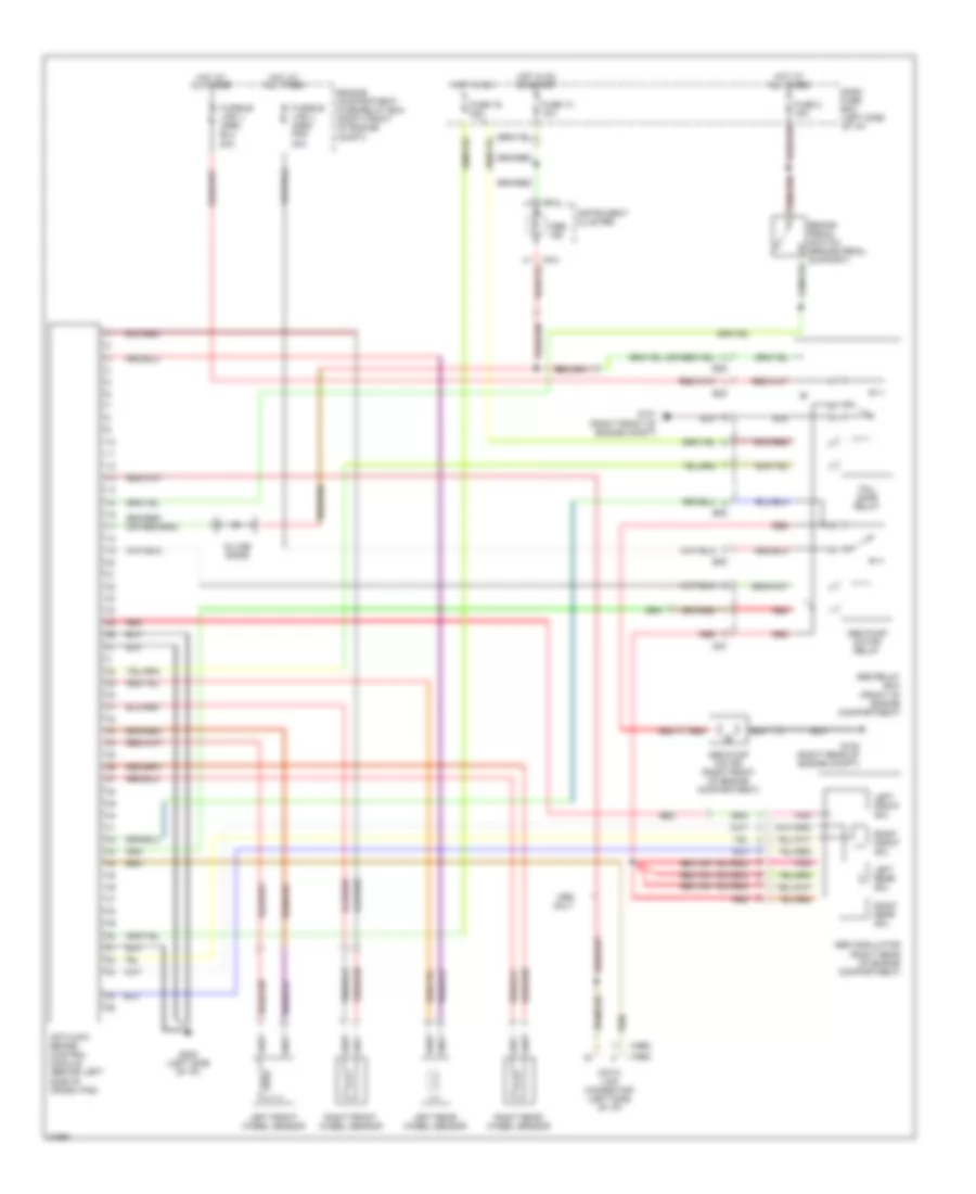
List of elements for Anti-lock Brake Wiring Diagrams for Hyundai Sonata GLS 1995:
- (1995)
- (1996)
- Abs ind
- Abs modulator (right rear of engine compartment)
- Abs pump motor (right front of engine compartment)
- Abs pump motor relay
- Abs relay box (front of engine compartment)
- Antilock brake control module (behind left side of crash pad)
- Ben
- Brake pedal switch (brake pedal support)
- Dash fuse box (left side of i/p)
- Data link connector (left side of i/p)
- E05
- E06
- Engine compartment fuse/relay box (right front of engine compt)
- Fail safe relay
- Fuse 10 10a
- Fuse 19 10a
- Fuse 2 15a
- Fusible link j (abs) pnk 30a
- G101 (right front of engine compt)
- G105 (right rear of engine compt)
- G202 (left side of i/p)
- Hot at all times
- Hot in on
- Hot in on or start
- I16-3
- In-line diode
- Instrument cluster
- Left front sol
- Left front wheel sensor
- Left rear sol
- Left rear wheel sensor
- M87
- Only
- Pnk
- Red
- Right front sol
- Right front wheel sensor
- Right rear sol
- Right rear wheel sensor
 Čeština
 Dansk
Dansk Deutsch
 Ελληνικά
 English
 Español
 Suomi
Suomi Français
 Français
 עברית
עברית Hrvatski
 Magyar
 Italiano
 日本語
日本語 한국어
한국어 Nederlands
 Polski
 Português
 Português
 Română
 Русский
 Slovenčina
 Slovenščina
 Svenska
 Türkçe
 中文 (中国)
 English