ANTI-LOCK BRAKES
Anti-lock Brakes Wiring Diagram for Hyundai XG350 2004
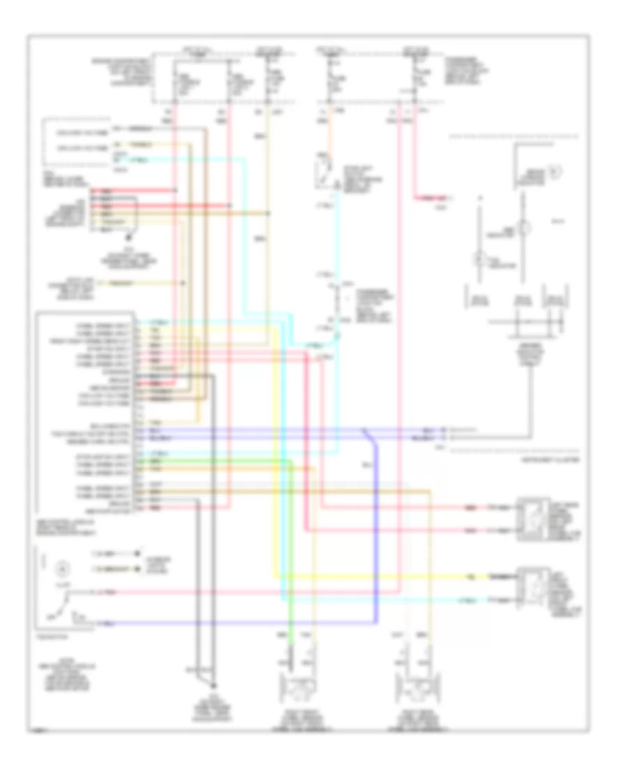
List of elements for Anti-lock Brakes Wiring Diagram for Hyundai XG350 2004:
- Abs control module (right rear of engine compartment)
- Abs fuse 10a
- Abs fusible link 1 30a
- Abs fusible link 2 30a
- Abs indicator
- Abs pump motor
- Abs solenoids
- Abs/ebd indicator control circuit
- Abs/ebd warn ind ctrl
- Air bleeding connector (left front of engine compt)
- Brake warning indicator
- C44-3
- C44-4
- Can (high voltage)
- Can (low voltage)
- Data link connector (dlc) (below left side of dash)
- Diagnosis
- Ecu check pin
- Engine compartment junction block (on left front of engine compartment)
- Front right speed sens out
- Fuse 10a
- Fuse 20a
- G12 (on right inner fender panel, near hood support)
- Ground
- Hot at all times
- Hot in on or start
- I/p-e
- I/p-h
- I/p-j
- I18-1
- I18-2
- Illum
- Instrument cluster
- Interior lights system
- Jc01
- Left front wheel sensor (on left front wheel hub assembly)
- Left rear wheel sensor (on left rear wheel hub assembly)
- Nca
- Note: abs control module contains: abs solenoids, tcs solenoids & abs pump motor
- Off
- Passenger compartment junction block (behind left end of dash)
- Pcm (behind lower center of dash)
- Pnk
- Red
- Right front wheel sensor (on right front wheel hub assembly)
- Right rear wheel sensor (on right rear wheel hub assembly)
- Solid state
- Start/on input
- Stoplamp sw input
- Stoplight switch (above brake pedal, on bracket)
- Tan
- Tcs indicator
- Tcs switch
- Tcs warn & tcs off ind ctrl
- Wheel speed input
 Čeština
 Dansk
Dansk Deutsch
 Ελληνικά
 English
 Español
 Suomi
Suomi Français
 Français
 עברית
עברית Hrvatski
 Magyar
 Italiano
 日本語
日本語 한국어
한국어 Nederlands
 Polski
 Português
 Português
 Română
 Русский
 Slovenčina
 Slovenščina
 Svenska
 Türkçe
 中文 (中国)
 English