ANTI-LOCK BRAKES
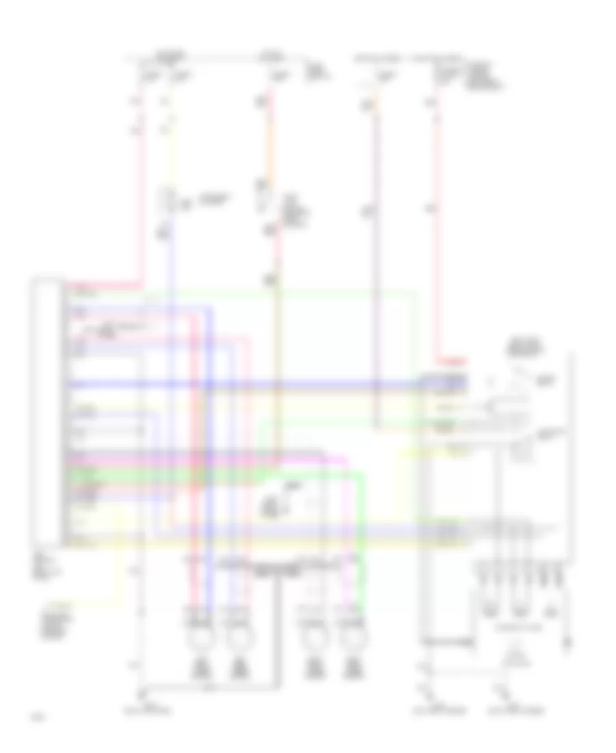
Anti-lock Brake Wiring Diagrams for Infiniti G20 1993
List of elements for Anti-lock Brake Wiring Diagrams for Infiniti G20 1993:
- (left front fender)
- (left shock
- (right front engine compt)
- (right front fender)
- (right kick panel)
- (right shock tower)
- Abs control
- Abs ind.
- Actuator
- Actuator relay
- All times
- Data link connector (left of steering column)
- Fuse 4 20a
- Fuse and fusible link box (left front engine compt)
- Fuse block (left i/p)
- Fuse u 10a
- Fuse x 20a
- Fuse z 10a
- Fusible link g 30a
- G100
- G101
- G102
- G103
- G203
- Hot at
- Hot at all times
- Hot in run or start
- Instrument cluster
- Left front wheel sensor
- Left rear wheel sensor
- Motor
- Motor relay
- Nca
- Pnk
- Red
- Relay box
- Right front wheel sensor
- Right rear wheel sensor
- Solenoid valves
- Stop lamp switch (on brake pedal support)
- Tower)
- Unit (right kick panel)
 Čeština
 Dansk
Dansk Deutsch
 Ελληνικά
 English
 Español
 Suomi
Suomi Français
 Français
 עברית
עברית Hrvatski
 Magyar
 Italiano
 日本語
日本語 한국어
한국어 Nederlands
 Polski
 Português
 Português
 Română
 Русский
 Slovenčina
 Slovenščina
 Svenska
 Türkçe
 中文 (中国)
 English