ANTI-LOCK BRAKES
Anti-lock Brakes Wiring Diagram for Infiniti G37 Sport 2008
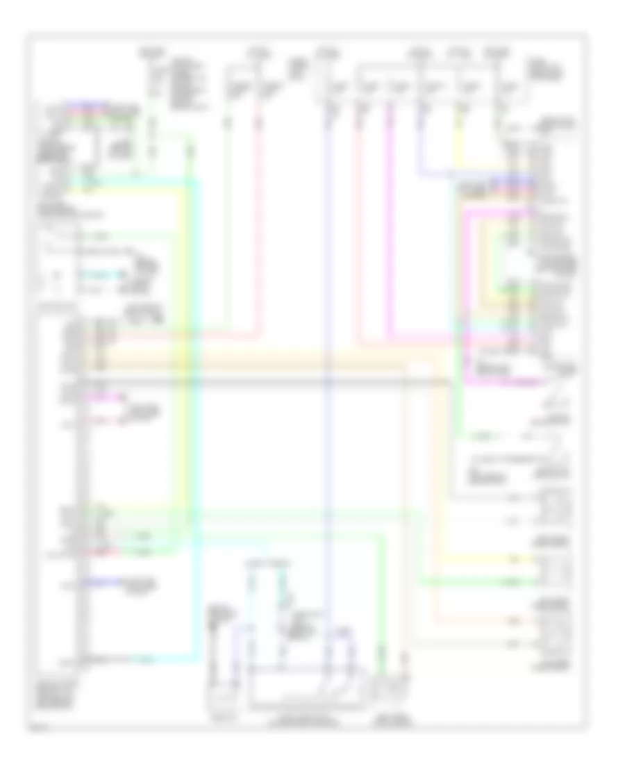
List of elements for Anti-lock Brakes Wiring Diagram for Infiniti G37 Sport 2008:
- (behind left side of dash) m55
- (behind right side of dash) m95
- (left rear of engine compt) e43
- 12c
- 12v
- Abs actuator & electric unit (control unit) (left rear of engine compt)
- Acc
- Amp lcd
- Amp meter
- Bat
- Bls
- Brake fluid level switch
- Brake sw
- Bus(h)
- Bus(l)
- Can-h
- Can-l
- Combination meter
- Computer data lines system
- Diag-k
- Dp fl
- Dp fr
- Dp rl
- Dp rr
- Ds fl
- Ds fr
- Ds rl
- Ds rr
- E103
- E46 (left rear of engine compt)
- Fuse & fusible link block
- Fuse 10a
- Fuse 11 10a
- Fuse 19 10a
- Fuse 3 10a
- Fuse 4 10a
- Fuse 6 10a
- Fuse 7 10a
- Fuse block (j/b) (behind left kick panel)
- Fusible link l 30a
- Fusible link m 50a
- Gnd
- Hot at all times
- Hot in acc or on
- Hot in on or start
- Ign
- Ill
- Interior lights system
- Ipdm e/r (intelligent power distribution module engine room) (at right rear of engine compt)
- Lcd amp
- Left front wheel sensor
- Left rear wheel sensor
- Level sw
- M11 (behind left end of dash)
- M66
- M67
- Meter amp
- Parking brake switch
- Pnk
- Red
- Resistor
- Right front wheel sensor
- Right rear wheel sensor
- Steering angle sensor (under left side of dash)
- Stop lamp switch (on brake pedal bracket)
- Ubmr
- Ubvr
- Unified meter & a/c amplifier (behind center of dash)
- Vdc off sw
- Vdc off switch
- W/ icc
- W/o icc
- Yaw rate/ side g sensor (under center console)
 Čeština
 Dansk
Dansk Deutsch
 Ελληνικά
 English
 English
 Español
 Suomi
Suomi Français
 Français
 עברית
עברית Hrvatski
 Magyar
 Italiano
 日本語
日本語 한국어
한국어 Nederlands
 Polski
 Português
 Română
 Русский
 Slovenčina
 Slovenščina
 Svenska
 Türkçe
 中文 (中国)
 Português