ANTI-LOCK BRAKES
Anti-lock Brake Wiring Diagrams for Isuzu VehiCROSS 1999
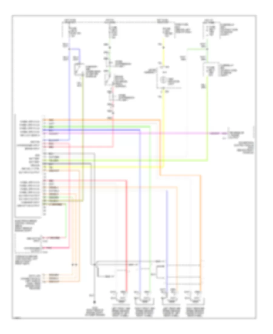
List of elements for Anti-lock Brake Wiring Diagrams for Isuzu VehiCROSS 1999:
- "abs" indicator light
- 4wd engaged input
- 4wd engaged output
- A12
- Abs active input
- Abs active output
- Abs ind lt ctrl
- B-5
- B-8
- Battery
- Brake input
- Brake switch (on brake pedal support)
- C-1
- C-43
- C-44
- Dash fuse box (behind left side of dash)
- Data link connector (dlc) (left side of dash, near engine hood release)
- Dlc input/output
- Electronic brake control module (ebcm) (right rear of engine compt)
- Fuse cb-13 stop light 15a
- Fuse cb-16 elec ign 15a
- Fuse cb-4 meter 10a
- Fuse eb-13 abs 20a
- Fuse eb-17 abs 40a
- Fuse/relay box (on right side of engine compt)
- G sensor - abs (under rear of center console)
- G sensor input
- G105 (right rear of engine compt, on inner fender)
- Gnd
- Ground
- Hot at all times
- Hot in on or start
- Ignition
- Left front abs speed sensor (inside of left front wheel)
- Left rear abs speed sensor (inside of left rear wheel)
- Meter assembly
- Noise suppression filter 1
- Pnk
- Powertrain control module (pcm) (behind front console)
- Red
- Rev/low gear in
- Reverse or l range output
- Right front abs speed sensor (inside of right front wheel)
- Right rear abs speed sensor (inside of right rear wheel)
- Torque on demand (tod) control unit (below right front seat)
- Wheel spd in (hi)
- Wheel spd in (lo)
 Čeština
 Dansk
Dansk Deutsch
 Ελληνικά
 English
 Español
 Suomi
Suomi Français
 Français
 עברית
עברית Hrvatski
 Magyar
 Italiano
 日本語
日本語 한국어
한국어 Nederlands
 Polski
 Português
 Português
 Română
 Русский
 Slovenčina
 Slovenščina
 Svenska
 Türkçe
 中文 (中国)
 English