ANTI-LOCK BRAKES
Anti Lock Brake Wiring Diagram for Land Rover Discovery 3 HSE 2007
 https://portal-diagnostov.com/license.html
Automotive Electricians Portal FZCO
Automotive Electricians Portal FZCO
https://portal-diagnostov.com/license.html
https://portal-diagnostov.com/license.html
Automotive Electricians Portal FZCO
Automotive Electricians Portal FZCO
List of elements for Anti Lock Brake Wiring Diagram for Land Rover Discovery 3 HSE 2007:
- (right front wheel arch liner) c2603
- Abs ind
- Abs module (left rear of engine compt)
- Afs control module
- Air suspension control module (base of left "a" pillar)
- Bla
- Bls
- C0040
- C0582 red
- C0867l
- C2114
- C2627 (right "a" pillar)
- C3196
- Can h
- Can l
- Can-h
- Can-l
- Center console switch pack
- Center fascia switch pack
- Central junction box (right side of dash)
- Computer data lines system
- Diagnostic socket (under left side of dash)
- Dpfl
- Dpfr
- Dprl
- Dprr
- Dsc switch
- Dsfl
- Dsfr
- Dsrl
- Dsrr
- Engine junction box (under engine compt fuse box)
- Exterior lights system
- Fuse 15a
- Fuse 25a
- Fuse 5a
- Fusible link 9 40a
- Gnd
- Hdc sw
- Hill descent relay
- Hill descent switch
- Hot at all times
- Hot in run
- Ign
- Instrument cluster
- K-line
- Left front wheel speed sensor (left front wheelwell)
- Left rear wheel speed sensor (below left rear wheelwell)
- M gnd
- Mdo-2
- Navigation system module (under front passenger's seat)
- Nca
- Red
- Reset
- Right front wheel speed sensor (right front wheelwell)
- Right rear wheel speed sensor (below right rear wheelwell)
- Sin 1
- Sot 1
- Speed control module
- Steering angle sensor (on underside of steering column)
- Stop lamp switch (at top of brake pedal assembly)
- Tcsaus
- Ubmr
- Ubvr
- Vso
- Yaw rate sensor (under center console)
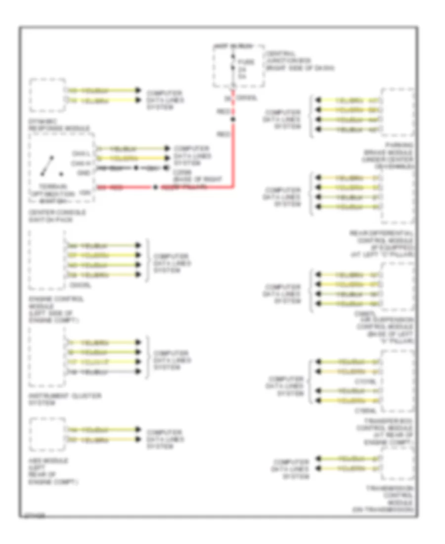
Terrain Response Wiring Diagram for Land Rover Discovery 3 HSE 2007
List of elements for Terrain Response Wiring Diagram for Land Rover Discovery 3 HSE 2007:
- Abs module (left rear of engine compt)
- Air suspension control module (base of left "a" pillar)
- C0583l
- C0635l
- C0867l
- C1319l
- C1854l
- C2598 (base of right "b" pillar)
- Can h
- Can l
- Center console switch pack
- Central junction box (right side of dash)
- Computer data lines system
- Dynamic response module
- Engine control module (left side of engine compt)
- Fuse 5a
- Gnd
- Hot in run
- Ign
- Instrument cluster system
- Parking brake module (under center of vehicle)
- Rear differential control module (if equipped) (at left "c" pillar)
- Red
- Terrain optimization switch
- Transfer box control module (at rear of engine compt)
- Transmission control module (on transmission)

 Čeština
 Dansk
Dansk Deutsch
 Ελληνικά
 English
 Español
 Suomi
Suomi Français
 Français
 עברית
עברית Hrvatski
 Magyar
 Italiano
 日本語
日本語 한국어
한국어 Nederlands
 Polski
 Português
 Português
 Română
 Русский
 Slovenčina
 Slovenščina
 Svenska
 Türkçe
 中文 (中国)