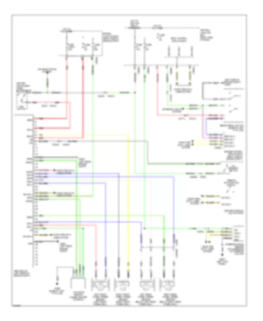
ANTI-LOCK BRAKES
Anti-lock Brakes Wiring Diagram for Land Rover Discovery 4 2013
List of elements for Anti-lock Brakes Wiring Diagram for Land Rover Discovery 4 2013:
- (left side of engine compt) c2564
- Abs module (left rear of engine compt)
- Air conditioning system
- Body control module (bcm)
- Brake pedal switch (base of left "a" pillar)
- Brk sw 1
- Brk sw 2
- C0047l
- C0223l
- C0559 (base of left "a" pillar)
- C0570l
- C0583l
- C0584l
- C0585l
- C0586l
- C0635l
- C0868s c0903
- C2238l
- C2240l
- C2243l
- C2245l
- C2293
- C2294sb
- C2411l
- C2412l
- C2443 c2444l
- C2603 (left rear engine compt)
- C2627 (left kick panel)
- Can h
- Can l
- Canm2
- Canp2
- Center console switch pack
- Center instrument panel switch pack
- Central junction box (right side of dash)
- Computer data
- Computer data lines system
- Diagk
- Dphl
- Dphr
- Dpvl
- Dpvr
- Dsc switch
- Dshl
- Dshr
- Dsvl
- Dsvr
- Engine control module (ecm) (right side of engine compt)
- Engine junction box (right side of engine compt)
- Exterior lights system
- Fuse 10a
- Fuse 25a
- Fuse 5a
- Fuse link 9 40a
- Gnd
- Hid
- Hill descent switch
- Hot at all times
- Hot w/ ignition relay energized
- Hs can h
- Hs can l
- Ign
- Left front wheel speed sensor (left front wheelwell)
- Left rear wheel speed sensor (below left rear wheelwell)
- Lines system
- Mgnd
- Nca
- Pata
- Red
- Right front wheel speed sensor (right front wheelwell)
- Right rear wheel speed sensor (below right rear wheelwell)
- Steering angle sensor (on underside of steering column)
- Terrain optimisation switch
- Ubmr
- Ubvr
- Yaw rate sensor (under center console)
 Čeština
 Dansk
Dansk Deutsch
 Ελληνικά
 English
 Español
 Suomi
Suomi Français
 Français
 עברית
עברית Hrvatski
 Magyar
 Italiano
 日本語
日本語 한국어
한국어 Nederlands
 Polski
 Português
 Português
 Română
 Русский
 Slovenčina
 Slovenščina
 Svenska
 Türkçe
 中文 (中国)
 English