ANTI-LOCK BRAKES
Anti Lock Brake Wiring Diagram for Land Rover Range Rover 2013
 https://portal-diagnostov.com/license.html
Automotive Electricians Portal FZCO
Automotive Electricians Portal FZCO
https://portal-diagnostov.com/license.html
https://portal-diagnostov.com/license.html
Automotive Electricians Portal FZCO
Automotive Electricians Portal FZCO
List of elements for Anti Lock Brake Wiring Diagram for Land Rover Range Rover 2013:
- (left front corner of engine compt) g1d129ar
- Abs module (left front corner of engine compt)
- Brake diag sw
- Brake diagnostic switch
- Brake pedal switch (at top of brake pedal assembly)
- Brake sw sig
- C1bb01b
- C2bp01a
- C2bp01b
- C2bp01f
- C2bp01g
- C2mc01a
- C31-j1
- C31-j2
- C44-a1
- C44-a2
- Central junction box (behind left side of dash)
- Computer data lines system
- Engine junction box (right rear corner of engine compt)
- Exterior lights system
- Fl pwr
- Fl rtn
- Fr pwr
- Fr rtn
- Fuse 5a
- Fusible link 7 40a
- Fusible link 9 30a
- G1d129al (left front corner of engine compt)
- G2d233 (left end of dash)
- Gnd
- Hot at all times
- Hot w/ ignition relay energized
- Hs can h
- Hs can l
- Ign
- Imu can h
- Imu can l
- Instrument cluster
- Left front wheel speed sensor (on left front wheel hub assembly)
- Left rear wheel speed sensor (on left rear wheel hub assembly)
- Ms can h
- Ms can l
- Nca
- Outh
- Outl
- Pump gnd
- Red
- Right front wheel speed sensor (on right front wheel hub assembly)
- Right rear wheel speed sensor (on right rear wheel hub assembly)
- Rl pwr
- Rl rtn
- Rr pwr
- Rr rtn
- Stop lamp switch
- Valve gnd
- Vbatt
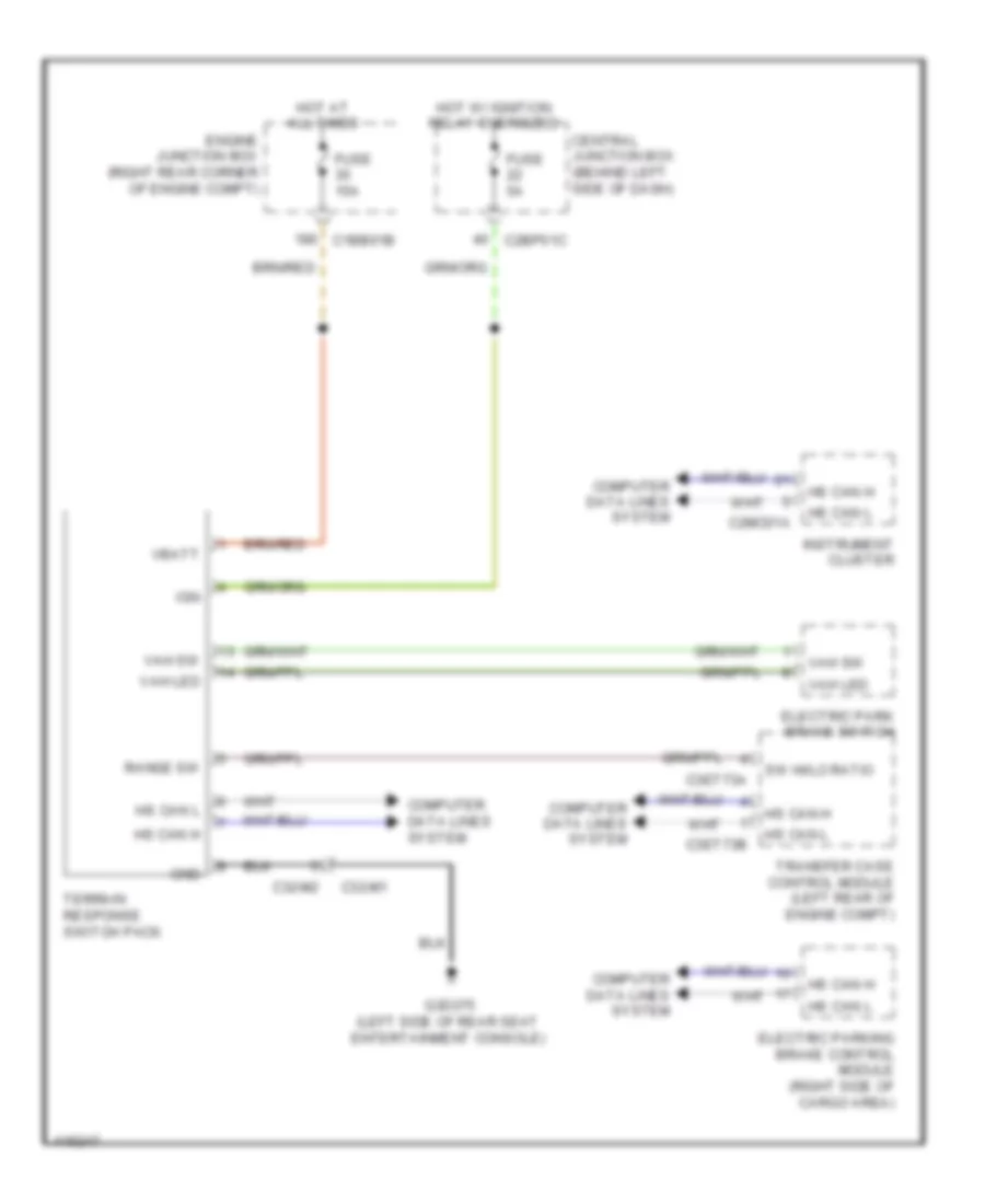
Terrain Response Wiring Diagram for Land Rover Range Rover 2013
List of elements for Terrain Response Wiring Diagram for Land Rover Range Rover 2013:
- C1bb01b
- C2bp01c
- C2mc01a
- C32-m1
- C32-m2
- C3et73a
- C3et73b
- Central junction box (behind left side of dash)
- Computer data lines system
- Electric park brake switch
- Electric parking brake control module (right side of cargo area)
- Engine junction box (right rear corner of engine compt)
- Fuse 15a
- Fuse 5a
- G3d375 (left side of rear seat entertainment console)
- Gnd
- Hot at all times
- Hot w/ ignition relay energized
- Hs can h
- Hs can l
- Ign
- Instrument cluster
- Range sw
- Sw hi/lo ratio
- Terrain response switch pack
- Transfer case control module (left rear of engine compt)
- Vah led
- Vah sw
- Vbatt

 Čeština
 Dansk
Dansk Deutsch
 Ελληνικά
 English
 Español
 Suomi
Suomi Français
 Français
 עברית
עברית Hrvatski
 Magyar
 Italiano
 日本語
日本語 한국어
한국어 Nederlands
 Polski
 Português
 Português
 Română
 Русский
 Slovenčina
 Slovenščina
 Svenska
 Türkçe
 中文 (中国)