ANTI-LOCK BRAKES
Anti-lock Brakes Wiring Diagram for Land Rover Range Rover HSE 2004
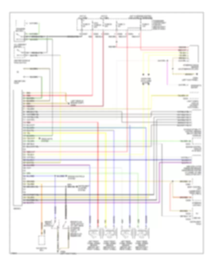
List of elements for Anti-lock Brakes Wiring Diagram for Land Rover Range Rover HSE 2004:
- (left rear of engine compt) c0362
- Abs ind
- Abs modulator pressure sensor (near brake master cylinder, on abs modulator unit)
- Abs return pump
- Abs-ecu
- Body control unit (under right front seat)
- Brake fluid level switch (at left rear of engine compt, on top of brake fluid reservoir)
- Brake pedal switch
- C0230
- C0234
- C0331
- C0554 (left kick panel)
- C0580
- C0583
- C0584
- C0586
- C0587
- C0661
- C0697
- C2040
- C2055
- Center console pack switch
- Computer data lines system
- Diagnostic socket
- Dynamic stability control sensor (below center console)
- Engine control module (in "e" box)
- Engine controls system
- Fuse 13 5a
- Fuse 37 5a
- Fuse 51 10a
- Fuse 55 30a
- Headlights system
- Hill descent switch
- Hot at all times
- Hot w/ engine control module relay energized
- Instrument cluster system
- Instrument pack
- Left front wheel speed sensor (behind left front wheel)
- Left rear wheel speed sensor (behind left rear wheel)
- Light check module (on right kick panel)
- Maxi fuse 63 50a
- Navigation ecu
- Passenger compartment fuse box (behind right side of dash)
- Red
- Right front wheel speed sensor (behind right front wheel)
- Right rear wheel speed sensor (behind right rear wheel)
- Steering angle sensor (on steering column)
- Steering lock ecu
- Transfer box ecu
 Čeština
 Dansk
Dansk Deutsch
 Ελληνικά
 English
 Español
 Suomi
Suomi Français
 Français
 עברית
עברית Hrvatski
 Magyar
 Italiano
 日本語
日本語 한국어
한국어 Nederlands
 Polski
 Português
 Português
 Română
 Русский
 Slovenčina
 Slovenščina
 Svenska
 Türkçe
 中文 (中国)
 English