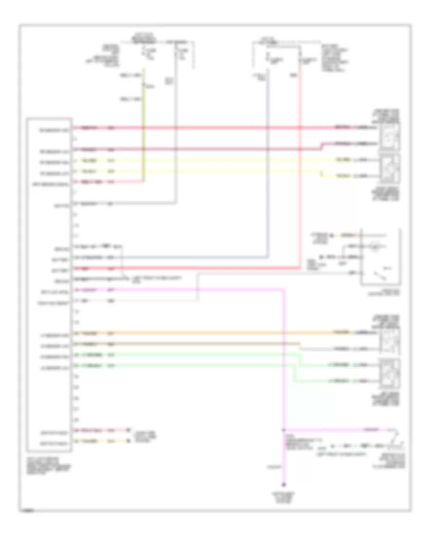
ANTI-LOCK BRAKES
Anti-lock Brake Wiring Diagrams for Lincoln Town Car Executive 2001
List of elements for Anti-lock Brake Wiring Diagrams for Lincoln Town Car Executive 2001:
- (inboard side of wheel hub) left front brake sensor
- (inboard side of wheel hub) right rear brake sensor
- (left front of eng compt)
- (left front of eng compt) g100
- Anti-lock brake control module (right front of engine compartment, behind radiator)
- Battery
- Battery junction box (left side of engine compartment, front of wheelwell)
- Bk fluid level
- Bpp sensor signal
- Brake fluid level switch (on brake fluid reservoir)
- Central junction box (behind dash, left of steering column)
- Computer data lines syetem
- Fuse 10a
- Fuse 27 20a
- Fuse 7.5a
- Fuse 9 40a
- G100
- G200 (left kick panel)
- Ground
- Hot at all times
- Hot in run
- Hot with brake pedal depressed
- Ignition
- Instrument cluster system
- Interior lights system
- Left rear brake sensor (inboard side of wheel hub)
- Lf sensor high
- Lr sensor high
- Lr sensor low
- Nca
- Red
- Red/pnk
- Rf sensor high
- Rf sensor low
- Right front brake sensor (inboard side of wheel hub)
- Rr sensor high
- Rr sensor low
- S108
- S137
- S164 (near breakout to brake fluid level switch)
- S207
- S234
- Scp data bus +
- Scp data bus -
- Traction assist
- Traction control switch
 Čeština
 Dansk
Dansk Deutsch
 Ελληνικά
 English
 Español
 Suomi
Suomi Français
 Français
 עברית
עברית Hrvatski
 Magyar
 Italiano
 日本語
日本語 한국어
한국어 Nederlands
 Polski
 Português
 Português
 Română
 Русский
 Slovenčina
 Slovenščina
 Svenska
 Türkçe
 中文 (中国)
 English