ANTI-LOCK BRAKES
Anti-lock Brake Wiring Diagrams for Mitsubishi Expo 1995
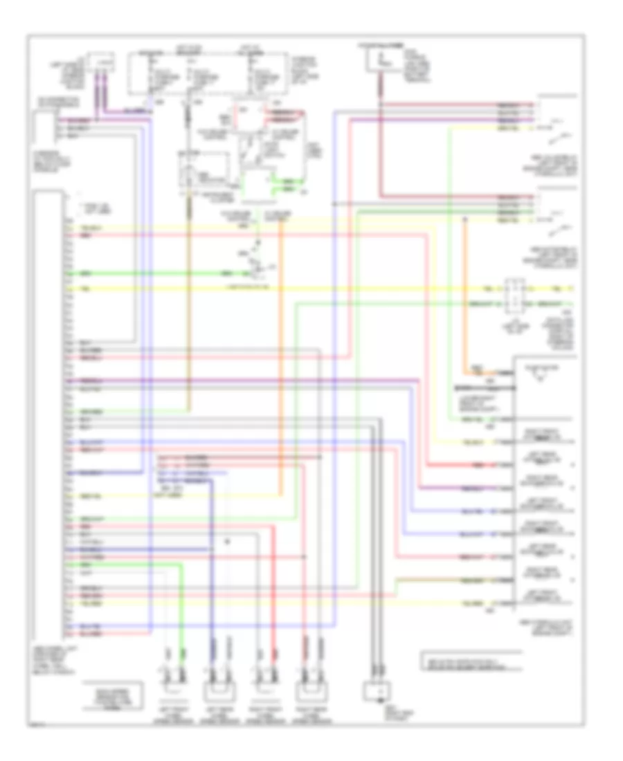
List of elements for Anti-lock Brake Wiring Diagrams for Mitsubishi Expo 1995:
- (left side of i/p)
- (lower right front of engine compt.)
- (not used)
- (not used- 2 pin)
- 60a
- A64
- A65
- Abs conrol unit (forward of right rear
- Abs hydraulic unit (left front of engine compt.)
- Abs indicator
- Abs motor relay (left front of engine compt. near hydraulic unit)
- Abs valve relay (left front of engine compt. near hydraulic unit)
- Below window)
- C38
- C58
- C61
- C69
- Data link connector (partial) (right of steering column)
- E63
- E63 22 pin: expo fwd only e72 20 pin: except expo fwd
- E72
- Each speed sensor has twisted wire pairs
- G sensor (w/ awd only) (below floor console)
- G101
- G201 (right end of dash)
- Hot at all times
- Hot in on
- Hot in on or start
- Instrument cluster
- Interior junction block (left side of i/p)
- J/c
- J/c (left side of i/p)
- J/c (left side of i/p, near interior junction block)
- Left front exhaust valve
- Left front intake valve
- Left front wheel speed sensor
- Left rear exhaust valve
- Left rear intake valve
- Left rear wheel speed sensor
- Main fusible link (abs) (positive battery terminal)
- Multi- purpose fuse 11 10a
- Multi- purpose fuse 17 15a
- Multi- purpose fuse 3 10a
- Nca
- No connection on fwd models
- Pins 1-29 not used
- Pump motor
- Red
- Right front exhaust valve
- Right front intake valve
- Right front wheel speed sensor
- Right rear exhaust valve
- Right rear intake valve
- Right rear wheel speed sensor
- Stop light switch
- W/ cruise control
- W/o cruise control
- Wheel well,
 Čeština
 Dansk
Dansk Deutsch
 Ελληνικά
 English
 Español
 Suomi
Suomi Français
 Français
 עברית
עברית Hrvatski
 Magyar
 Italiano
 日本語
日本語 한국어
한국어 Nederlands
 Polski
 Português
 Português
 Română
 Русский
 Slovenčina
 Slovenščina
 Svenska
 Türkçe
 中文 (中国)
 English