ANTI-LOCK BRAKES
Anti-lock Brake Wiring Diagrams for Mitsubishi Expo LRV 1994
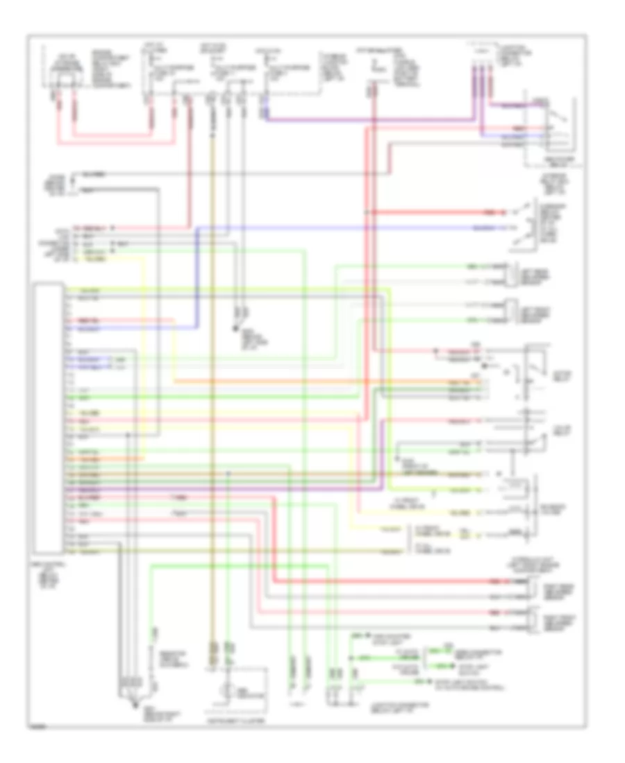
List of elements for Anti-lock Brake Wiring Diagrams for Mitsubishi Expo LRV 1994:
- (under left side of i/p)
- 60a
- A09x
- A26
- A27
- Abs control unit (below center of i/p)
- Abs indicator
- Abs power relay
- C05
- C29x
- C57
- C58
- C61
- C64
- C66
- C67
- D01
- D03
- Data link connector
- Diode (behind center of i/p)
- Engine compartment relay box (right side of engine compartment)
- G sensor (below center of i/p) (w/ all wheel drive)
- G100 (front of left fender)
- G201 (behind right side of i/p)
- G202 (behind left side of i/p)
- High mounted stop light
- Hot at all times
- Hot in on
- Hot in on or start
- Hydraulic unit (left front engine compartment)
- Instrument cluster
- Interior junction block (below left i/p)
- Interior relay box (below left i/p)
- Iod or storage connector
- Junction connector (below left i/p)
- Left front abs speed sensor
- Left rear abs speed sensor
- Main fusible link (abs) (positve battery terminal)
- Motor relay
- Multi-purpose fuse 11 10a
- Multi-purpose fuse 19 10a
- Multi-purpose fuse 3 10a
- Nca
- Open connector (below i/p)
- Red
- Resistor (above glovebox)
- Right front abs speed sensor
- Right rear abs speed sensor
- Solenoid valves
- Stop light
- Stop light switch (w/ auto-cruise control)
- Switch
- Valve relay
- W/ all wheel drive
- W/ auto- cruise
- W/ front wheel drive
- W/o auto- cruise
 Čeština
 Dansk
Dansk Deutsch
 Ελληνικά
 English
 Español
 Suomi
Suomi Français
 Français
 עברית
עברית Hrvatski
 Magyar
 Italiano
 日本語
日本語 한국어
한국어 Nederlands
 Polski
 Português
 Português
 Română
 Русский
 Slovenčina
 Slovenščina
 Svenska
 Türkçe
 中文 (中国)
 English