ANTI-LOCK BRAKES
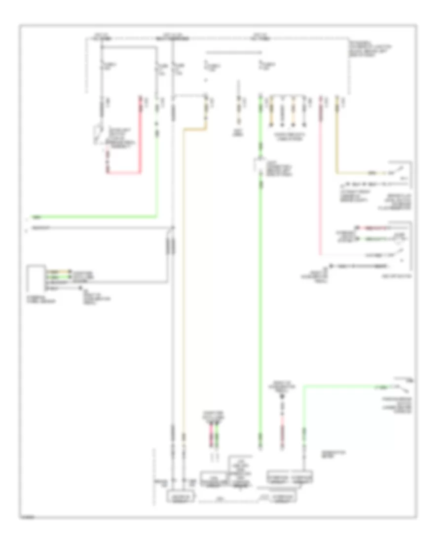
Anti-lock Brakes Wiring Diagram, without Active Skid Control for Mitsubishi Lancer DE 2009
 https://portal-diagnostov.com/license.html
Automotive Electricians Portal FZCO
Automotive Electricians Portal FZCO
https://portal-diagnostov.com/license.html
https://portal-diagnostov.com/license.html
Automotive Electricians Portal FZCO
Automotive Electricians Portal FZCO
List of elements for Anti-lock Brakes Wiring Diagram, without Active Skid Control for Mitsubishi Lancer DE 2009:
- (behind left side of dash) g13
- (behind right kick panel)
- (brake)
- (on brake fluid reservoir) brake fluid level switch
- (on left front wheel hub assembly)
- Abs ind
- Abs solenoid valve
- Abs-ecu (right rear of engine compt)
- Brake ind
- C-301
- C-304
- C-312
- C-317
- Can transceiver circuit
- Combination meter
- Computer data lines system
- Cpu
- Engine compartment fuse/relay box (left side of engine compt)
- Etacs-ecu (on rear of junction block, behind left end of dash)
- Fuse 15a
- Fuse 7.5a
- Fusible link 26 40a
- Fusible link 27 30a
- G1 (at right front corner of engine compt)
- Hot at all times
- Hot in on or start
- Hydraulic unit
- Ig1 relay
- Interface circuit
- Joint connector (can-01) (behind left side of dash)
- Led (abs)
- Led drive circuit
- Left front wheel speed sensor
- Left rear wheel speed sensor (at left rear wheel hub assembly)
- Motor m
- Nca
- Parking brake switch (under center console)
- Pnk
- Red
- Right front wheel speed sensor (on right front wheel hub assembly)
- Right rear wheel speed sensor (at right rear wheel hub assembly)
- Stoplight switch (under left side of dash)
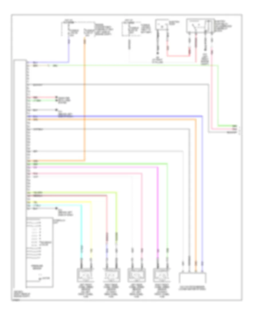
2.0L
2.0L, Anti-lock Brakes Wiring Diagram, with Active Skid Control (1 of 2) for Mitsubishi Lancer DE 2009
List of elements for 2.0L, Anti-lock Brakes Wiring Diagram, with Active Skid Control (1 of 2) for Mitsubishi Lancer DE 2009:
- Asc-ecu (right rear of engine compt)
- Computer data lines system
- Engine compartment fuse/relay box (left side of engine compt)
- Fusible link 26 40a
- Fusible link 27 30a
- G & yaw rate sensor (lower center of dash)
- G13 (behind left side of dash)
- Hot at all times
- Hydraulic unit
- Left front wheel speed sensor (on left front wheel hub)
- Left rear wheel speed sensor (at left rear wheel hub)
- Motor m
- Nca
- Pnk
- Pressure sensor
- Right front wheel speed sensor (on right front wheel hub)
- Right rear wheel speed sensor (at right rear wheel hub)
- Solenoid valve
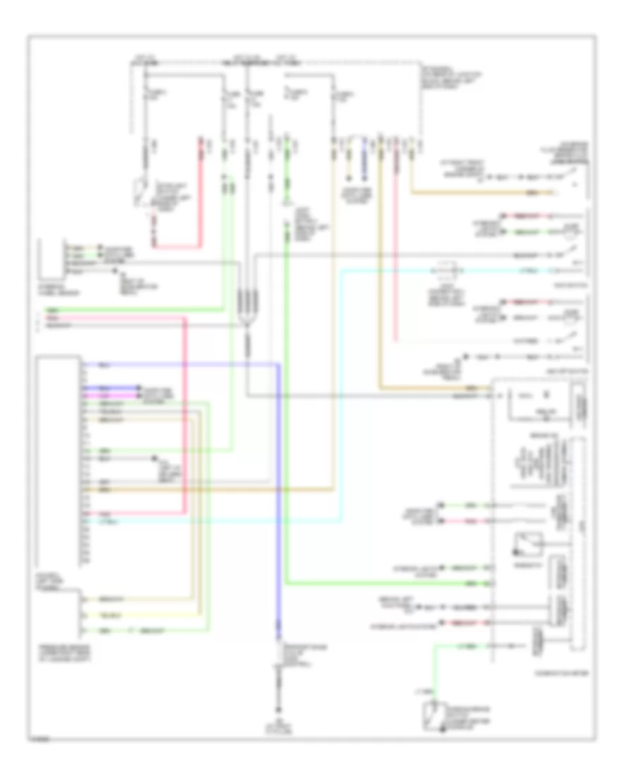
2.0L, Anti-lock Brakes Wiring Diagram, with Active Skid Control (2 of 2) for Mitsubishi Lancer DE 2009
List of elements for 2.0L, Anti-lock Brakes Wiring Diagram, with Active Skid Control (2 of 2) for Mitsubishi Lancer DE 2009:
- (at right front corner of engine compt)
- (not used)
- (right of accelerator pedal) g5
- Abs ind
- Asc off switch
- Brake fluid level switch (on brake fluid reservoir)
- Brake ind
- C-301
- C-304
- C-311
- C-312
- C-313
- C-315
- C-317
- Can transceiver circuit
- Combination meter
- Computer data lines system
- Cpu
- Etacs-ecu (on rear of junction block, behind left end of dash)
- Fuse 10a
- Fuse 2 15a
- Fuse 7.5a
- Fuse 8 7.5a
- Fuse 9 15a
- G5 (right of accelerator pedal)
- Hot at all times
- Hot w/ ig1 relay energized
- Illum
- Interface circuit
- Interior lights system
- Joint connector 3 (behind left side of dash)
- Lcd (asc off) (asc operation) (asc warning) (brake)
- Led drive circuit
- Parking brake switch (under center console)
- Pnk
- Red
- Steering wheel sensor
- Stoplight switch (top of brake pedal assembly)
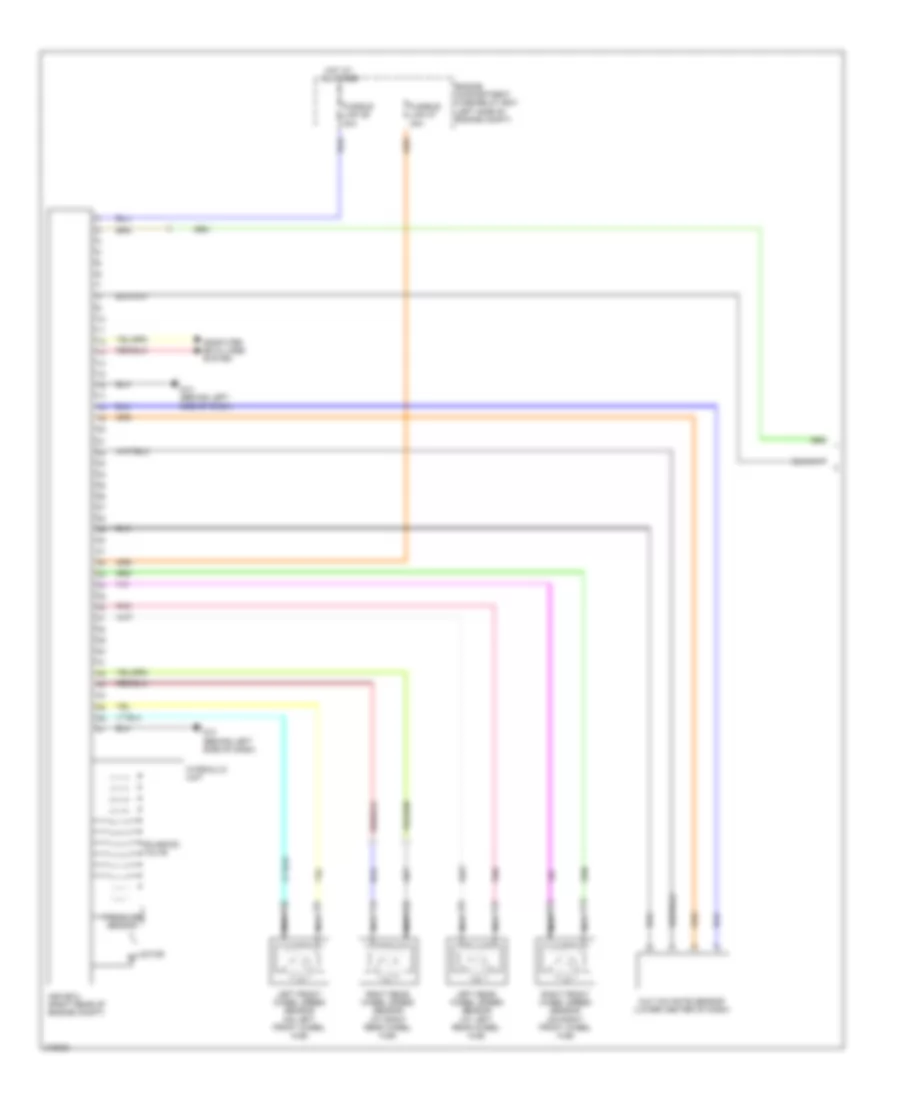
2.0L TURBO
2.0L Turbo, Anti-lock Brakes Wiring Diagram, with Active Skid Control (1 of 2) for Mitsubishi Lancer DE 2009
List of elements for 2.0L Turbo, Anti-lock Brakes Wiring Diagram, with Active Skid Control (1 of 2) for Mitsubishi Lancer DE 2009:
- Asc-ecu (right rear of engine compt)
- Computer data lines system
- Electric pump
- Electric pump relay (on underhood fuse/relay block)
- Engine compartment fuse/relay box (left side of engine compt)
- Fusible link 26 40a
- Fusible link 27 30a
- Fusible link 35 80a
- Fusible link box (next to battery)
- G & yaw rate sensor (lower center of dash)
- G13 (behind left side of dash)
- G18 (left front engine compt)
- G9 (at right "c" pillar)
- Hot at all times
- Hydraulic unit
- Left front wheel speed sensor (on left front wheel hub)
- Left rear wheel speed sensor (at left rear wheel hub)
- Motor m
- Nca
- Pnk
- Pressure sensor
- Red
- Right front wheel speed sensor (on right front wheel hub)
- Right rear wheel speed sensor (at right rear wheel hub)
- Solenoid valve
2.0L Turbo, Anti-lock Brakes Wiring Diagram, with Active Skid Control (2 of 2) for Mitsubishi Lancer DE 2009
List of elements for 2.0L Turbo, Anti-lock Brakes Wiring Diagram, with Active Skid Control (2 of 2) for Mitsubishi Lancer DE 2009:
- (abs)
- (acd)
- (asc off) (asc operation)
- (asc warning)
- (at right front corner of engine compt) g1
- (behind left kick panel) g14
- (brake)
- (gravel)
- (on brake fluid reservoir) brake fluid level switch
- (snow)
- (termac)
- Abs ind
- Asc off switch
- Awc switch
- Awc-ecu (left side of dash)
- Brake ind
- C-301
- C-304
- C-311
- C-312
- C-313
- C-315
- C-317
- Circuit interface
- Circuit transceiver can
- Combination meter
- Computer data lines system
- Cpu
- Etacs-ecu (on rear of junction block, behind left end of dash)
- Fuse 10a
- Fuse 2 15a
- Fuse 7.5a
- Fuse 8 7.5a
- Fuse 9 15a
- G12 (left of drivers seat)
- G5 (right of accelerator pedal)
- G9 (at right "c" pillar)
- Hot at all times
- Hot w/ ig1 relay energized
- Illum
- Interior lights system
- Joint conn- ector 3 (behind left side of dash)
- Joint connector 3 (behind left side of dash)
- Lcd
- Led drive circuit
- Parking brake switch (under center console)
- Pnk
- Pressure sensor (under right rear of luggage compt)
- Proportioning valve (acd control)
- Red
- Rheostat
- Steering wheel sensor
- Stoplight switch (under left side of dash)
2.4L
2.4L, Anti-lock Brakes Wiring Diagram, with Active Skid Control (1 of 2) for Mitsubishi Lancer DE 2009
List of elements for 2.4L, Anti-lock Brakes Wiring Diagram, with Active Skid Control (1 of 2) for Mitsubishi Lancer DE 2009:
- Asc-ecu (right rear of engine compt)
- Computer data lines system
- Engine compartment fuse/relay box (left side of engine compt)
- Fusible link 26 40a
- Fusible link 27 30a
- G & yaw rate sensor (lower center of dash)
- G13 (behind left side of dash)
- Hot at all times
- Hydraulic unit
- Left front wheel speed sensor (on left front wheel hub)
- Left rear wheel speed sensor (at left rear wheel hub)
- Motor m
- Nca
- Pnk
- Pressure sensor
- Right front wheel speed sensor (on right front wheel hub)
- Right rear wheel speed sensor (at right rear wheel hub)
- Solenoid valve
2.4L, Anti-lock Brakes Wiring Diagram, with Active Skid Control (2 of 2) for Mitsubishi Lancer DE 2009
List of elements for 2.4L, Anti-lock Brakes Wiring Diagram, with Active Skid Control (2 of 2) for Mitsubishi Lancer DE 2009:
- (at right front corner of engine compt)
- (not used)
- (right of accelerator pedal) g5
- Abs ind
- Asc off switch
- Brake fluid level switch (on brake fluid reservoir)
- Brake ind
- C-301
- C-304
- C-311
- C-312
- C-313
- C-315
- C-317
- Can transceiver circuit
- Combination meter
- Computer data lines system
- Cpu
- Etacs-ecu (on rear of junction block, behind left end of dash)
- Fuse 10a
- Fuse 2 15a
- Fuse 7.5a
- Fuse 8 7.5a
- Fuse 9 15a
- G5 (right of accelerator pedal)
- Hot at all times
- Hot w/ ig1 relay energized
- Illum
- Interface circuit
- Interior lights system
- Joint connector 3 (behind left side of dash)
- Lcd (asc off) (asc operation) (asc warning) (brake)
- Led drive circuit
- Parking brake switch (under center console)
- Pnk
- Red
- Steering wheel sensor
- Stoplight switch (top of brake pedal assembly)

 Čeština
 Dansk
Dansk Deutsch
 Ελληνικά
 English
 Español
 Suomi
Suomi Français
 Français
 עברית
עברית Hrvatski
 Magyar
 Italiano
 日本語
日本語 한국어
한국어 Nederlands
 Polski
 Português
 Português
 Română
 Русский
 Slovenčina
 Slovenščina
 Svenska
 Türkçe
 中文 (中国)