ANTI-LOCK BRAKES
Anti-lock Brakes Wiring Diagram for Mitsubishi Lancer ES 2007
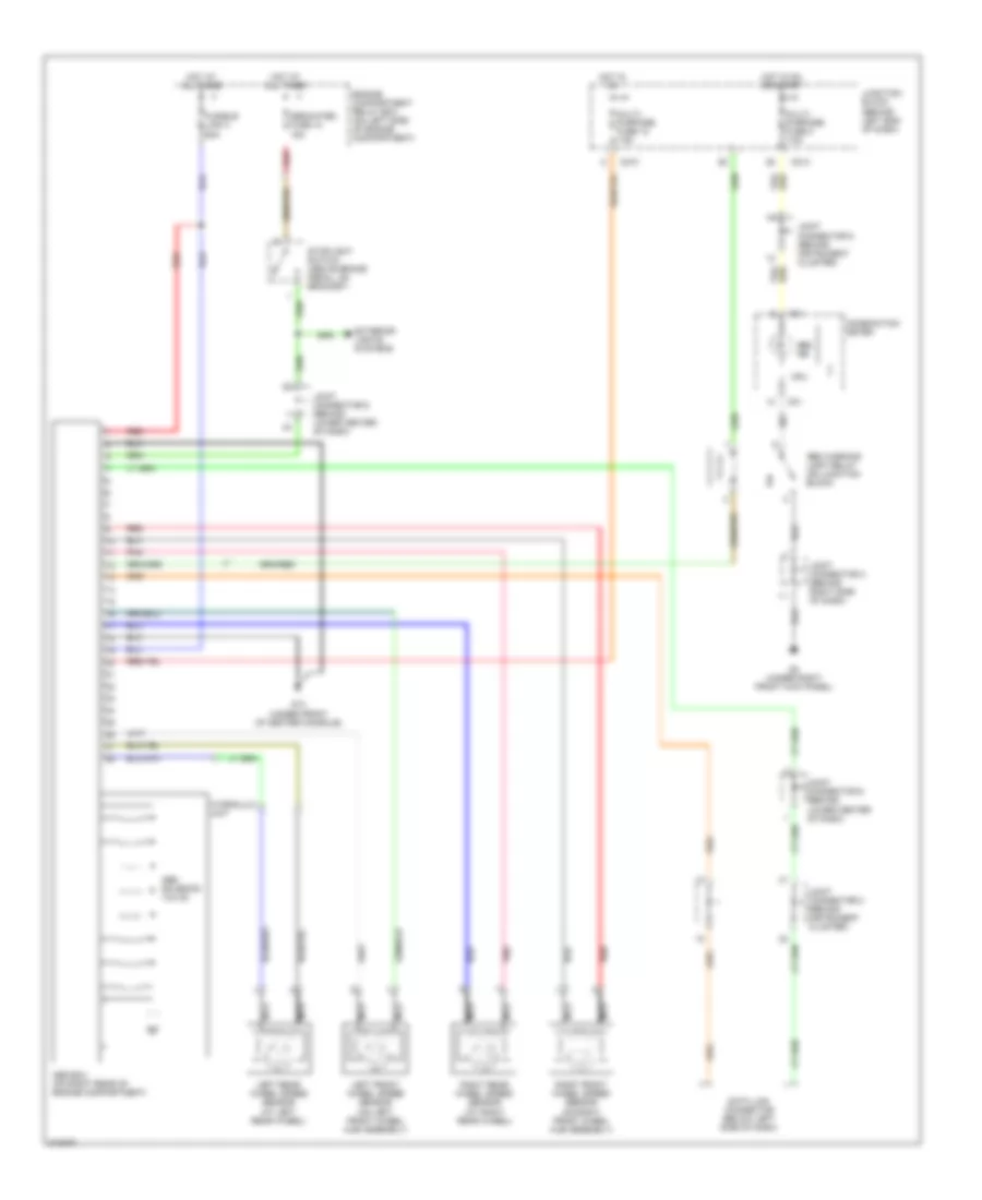
List of elements for Anti-lock Brakes Wiring Diagram for Mitsubishi Lancer ES 2007:
- Abs ecu (on right rear of engine compartment)
- Abs ind
- Abs solenoid valve
- Abs warning light relay (on junction block)
- C01
- C210
- C214
- Combination meter
- Cpu
- Data link connector (below left side of dash)
- Dedicated fuse 10 15a
- Engine compartment relay box (on left side of engine compartment)
- Exterior lights systems
- Fusible link 3 60a
- G14 (under front of center console)
- G3 (under right front kick panel)
- Hot at all times
- Hot in on
- Hot in on or start
- Hydraulic unit
- Joint connector 5 (behind instrument cluster)
- Joint connector 2 (behind instrument cluster)
- Joint connector 3 (behind right side of dash)
- Joint connector 6 (behind lower center of dash)
- Junction block (behind left end of dash)
- Left front wheel speed sensor (on left front wheel hub assembly)
- Left rear wheel speed sensor (at left rear wheel)
- Multi- purpose fuse 12 7.5a
- Multi- purpose fuse 2 7.5a
- Nca
- Pnk
- Red
- Right front wheel speed sensor (on right front wheel hub assembly)
- Right rear wheel speed sensor (at right rear wheel)
- Stoplight switch (above brake pedal, on bracket)
 Čeština
 Dansk
Dansk Deutsch
 Ελληνικά
 English
 Español
 Suomi
Suomi Français
 Français
 עברית
עברית Hrvatski
 Magyar
 Italiano
 日本語
日本語 한국어
한국어 Nederlands
 Polski
 Português
 Português
 Română
 Русский
 Slovenčina
 Slovenščina
 Svenska
 Türkçe
 中文 (中国)
 English