ANTI-LOCK BRAKES
Anti-Lock Brakes Wiring Diagram for Mitsubishi Montero 1998
 https://portal-diagnostov.com/license.html
Automotive Electricians Portal FZCO
Automotive Electricians Portal FZCO
https://portal-diagnostov.com/license.html
https://portal-diagnostov.com/license.html
Automotive Electricians Portal FZCO
Automotive Electricians Portal FZCO
List of elements for Anti-Lock Brakes Wiring Diagram for Mitsubishi Montero 1998:
- (left side of dash)
- (left side of dash) j/c 3
- (mounted on top of left rear wheelwell)
- (on bracket, on each wheel hub)
- (positive battery terminal)
- A39
- A40
- A76
- A77
- Abs control unit (mounted on top of right rear wheelwell, under metal plate)
- Abs indicator
- Abs motor relay
- Abs relay box (in right rear corner of engine compt)
- Abs valve relay
- C04
- C05
- C149
- C81
- C93
- C96
- Center differential lock detection switch (on trans)
- Combination meter
- Data link connector (behind left side of dash, near relay box)
- E13
- E14
- Engine control module (behind right kick panel)
- Exterior lights system (stop light switch)
- Free wheel engage switch (right side of eng compt)
- Fusible link 1 60a
- G sensor (in center console, rear of parking brake lever)
- G105 (right rear of engine compt)
- G121 (center of firewall)
- G402 (left rear wheelwell)
- Hot at all times
- Hot in run
- Hot in run or start
- Hydraulic unit (in right rear corner of engine compt)
- Iod or storage connector (in engine compartment relay box)
- J/c 1
- J/c 2 (left side of dash)
- J/c 3 (left side of dash)
- Junction block (behind left side of dash)
- Left front exhaust valve
- Left front intake valve
- Left front wheel speed sensor
- Left rear wheel speed sensor
- Multi- purpose fuse 11 10a
- Multi- purpose fuse 19 10a
- Multi- purpose fuse 7 10a
- Nca
- Pump motor
- Rear differential lock control unit
- Rear differential lock control unit jumper connector (above left rear wheelwell)
- Rear differential lock detection switch
- Rear exhaust valve
- Rear intake valve
- Red
- Right front exhaust valve
- Right front intake valve
- Right front wheel speed sensor
- Right rear wheel speed sensor
- Trans- missions system (4wd)
- W/ rear differential lock
- W/o rear differential lock
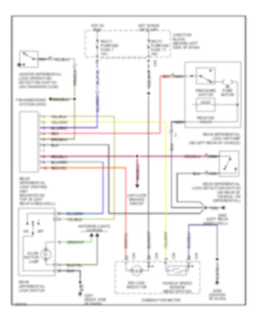
Differential Lock Wiring Diagram for Mitsubishi Montero 1998
List of elements for Differential Lock Wiring Diagram for Mitsubishi Montero 1998:
- (left rear wheelwell)
- Anti-lock brakes circuit
- C04
- C05
- C06
- C96
- Center differential lock operation detection switch (on transfer case)
- Combination meter
- G201 (right side of dash)
- G206 (center of dash)
- G402
- Hot in run
- Hot in run or start
- Illum- ination lamp
- Interior lights system
- Junction block (behind left side of dash)
- Multi- purpose fuse 11 10a
- Multi- purpose fuse 7 10a
- Nca
- Off
- Pressure switch
- Pump motor
- R/d lock indicator
- Rear differential lock air pump (on left rear of vehicle)
- Rear differential lock control unit (mounted on top of left rear wheelwell)
- Rear differential lock detection switch (on rear of vehicle, on differential)
- Rear differential lock switch
- Red
- Release valve
- Transmissions system (4wd)
- Vehicle speed sensor (reed switch)

 Čeština
 Dansk
Dansk Deutsch
 English
 English
 Español
 Suomi
Suomi Français
 Français
 עברית
עברית Hrvatski
 Magyar
 Italiano
 日本語
日本語 한국어
한국어 Nederlands
 Polski
 Português
 Português
 Română
 Русский
 Slovenčina
 Slovenščina
 Svenska
 Türkçe
 中文 (中国)