ANTI-LOCK BRAKES
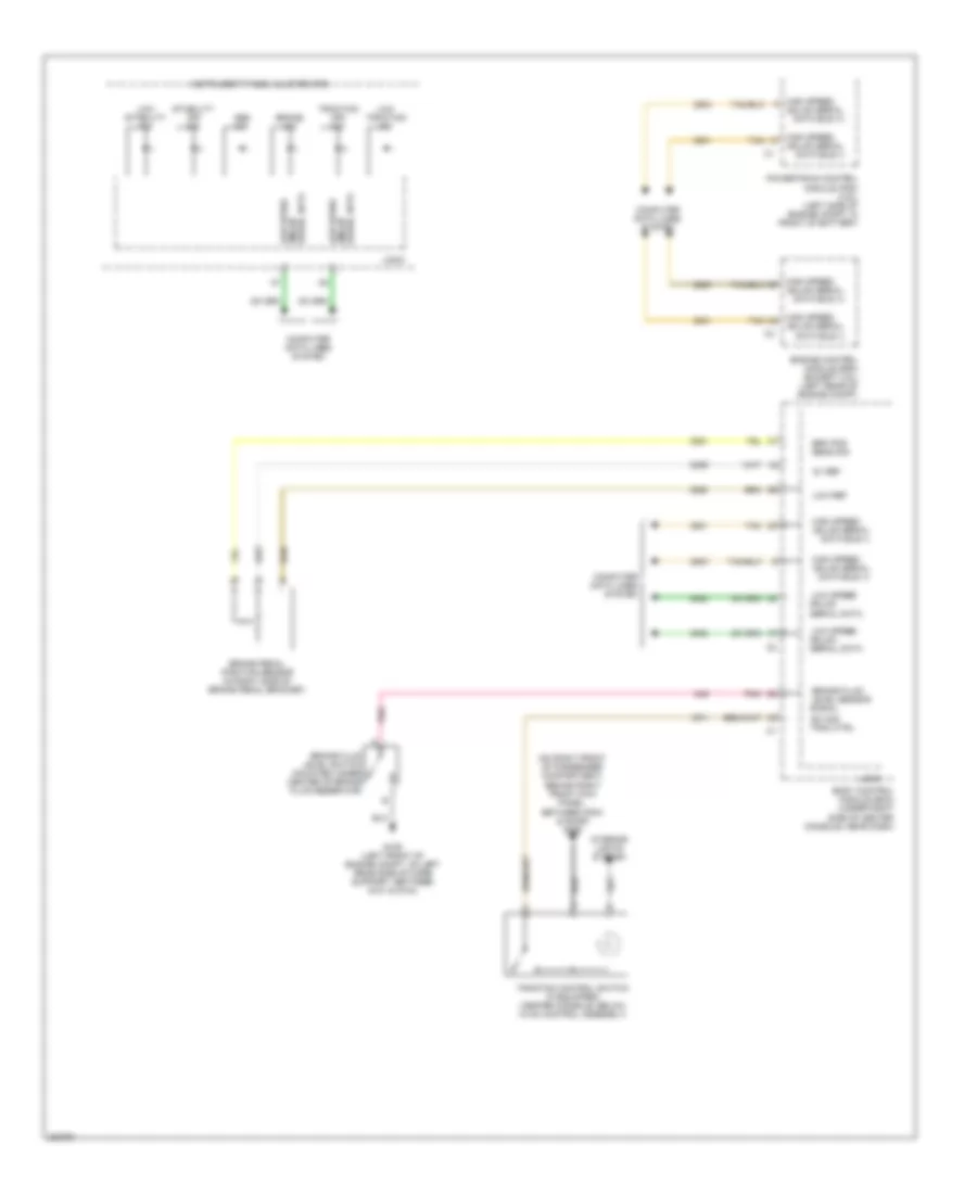
Anti-lock Brakes Wiring Diagram (1 of 2) for Pontiac G6 GTP 2006
 https://portal-diagnostov.com/license.html
Automotive Electricians Portal FZCO
Automotive Electricians Portal FZCO
https://portal-diagnostov.com/license.html
https://portal-diagnostov.com/license.html
Automotive Electricians Portal FZCO
Automotive Electricians Portal FZCO
List of elements for Anti-lock Brakes Wiring Diagram (1 of 2) for Pontiac G6 GTP 2006:
- (left front of engine compt, on left rear side of core support, between g101 & g104)
- 5v ref
- A10
- A11
- A12
- A13
- A14
- Abs fuse 15 10a
- Abs fuse 24 60a
- B10
- B11
- B12
- B13
- B14
- Bat
- Brake fluid pressure sensor (3.5l) (on electronic brake control module)
- Brake fluid pressure sig
- Brake pressure modulator valve (bpmv)
- C10
- C11
- C12
- C13
- C14
- Computer data lines system
- Electronic brake control module (ebcm) (left side of engine compt, mounted to back side of strut tower, part of brake pressure modulator valve (bpmv))
- G109
- Gmlan serial data (+)
- Gmlan serial data (-)
- Gnd
- Hot at all times
- Hot w/ run/ crank relay energized
- Ign 1 voltage
- Lat accel sig
- Lateral accelerometer sig
- Left front wheel speed sensor (wss) (in left front wheel hub)
- Left rear wheel speed sensor (wss) (in left rear wheel hub)
- Lf wheel sens sply voltage
- Lf wheel spd sens sig
- Low ref
- Lr wheel sens sply voltage
- Lr wheel spd sens sig
- Nca
- Pnk
- Pump mtr ctrl
- Rf wheel sens sply voltage
- Rf wheel spd sens sig
- Ride & handling - automatic electronic controlled
- Right front wheel speed sensor (wss) (in right front wheel hub)
- Right rear wheel speed sensor (in right rear wheel hub)
- Rr wheel sens sply voltage
- Rr wheel spd sens sig
- Sens sig yaw rate
- Sig gnd
- Steering wheel position sensor (left side of i/p, under base of steering column)
- Strng wheel pos sens sig 2
- Strng wheel pos sig 2
- Strng wheel pos sig a
- Strng wheel pos sig b
- Tan
- Underhood fuse block (in left side of engine compt)
- Yaw rate & lateral acceleration sensor (under center floor console)
- Yaw rate sens sig
Anti-lock Brakes Wiring Diagram (2 of 2) for Pontiac G6 GTP 2006
List of elements for Anti-lock Brakes Wiring Diagram (2 of 2) for Pontiac G6 GTP 2006:
- (on right front of passenger compartment, behind right front kick panel, between g304 & door) g305
- 5v ref
- Abs ind
- Body control module (bcm) (under right side of center console, near dash)
- Brake fluid
- Brake fluid level switch (mounted under center of brake fluid reservoir)
- Brake ind
- Brake pedal position sensor (in right side of brake pedal bracket)
- Brk pos sens sig
- Computer data lines system
- Engine control module (ecm) (except 3.5l) (left rear of engine compt)
- G109 (left front of engine compt, on left rear side of core support, between g101 & g104)
- Gmlan
- Gmlan serial data bus (+)
- Gmlan serial data bus (-)
- High speed
- Instrument panel cluster (ipc)
- Interior lights system
- Level sensor
- Logic
- Low ref
- Low speed
- Low speed gmlan
- Low stability ind
- Low traction ind
- Pnk
- Powertrain control module (pcm) (3.5l) (left side of engine compt, in front of battery)
- Serial data
- Serial data gmlan
- Signal
- Stability off ind
- Sw sig
- Tan
- Trac ctrl
- Traction control switch (if equipped) (center console, below hvac control assembly)
- Traction off ind

 Čeština
 Dansk
Dansk Deutsch
 Ελληνικά
 English
 Español
 Suomi
Suomi Français
 Français
 עברית
עברית Hrvatski
 Magyar
 Italiano
 日本語
日本語 한국어
한국어 Nederlands
 Polski
 Português
 Português
 Română
 Русский
 Slovenčina
 Slovenščina
 Svenska
 Türkçe
 中文 (中国)