ANTI-LOCK BRAKES
Anti-lock Brake Wiring Diagrams for Pontiac Grand Prix GT 1999
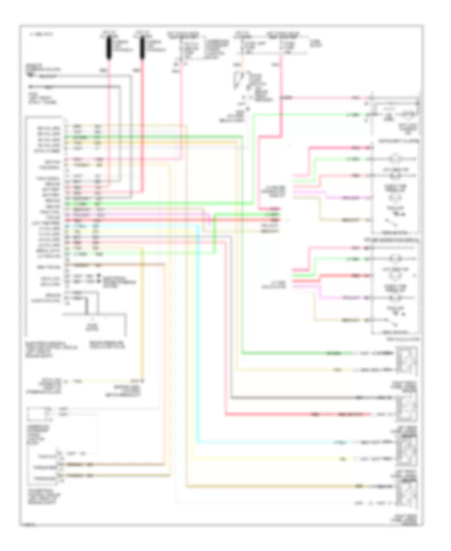
List of elements for Anti-lock Brake Wiring Diagrams for Pontiac Grand Prix GT 1999:
- (base of steering column) g202
- (engine harn, 4 cm from ebtcm breakout)
- (on brake pedal bracket)
- A/c clu/ abs ign fuse 10a
- Abs ind
- Anti-lock wanring ind
- B c1
- Battery
- Brake pressure modulator valve
- C 1995 vftc
- Check tire press ind
- Connector (right of steering column)
- Data link
- Driver information display
- Electronic brake & traction control module (left side of engine compt)
- Electronic power steering system
- Fuse block
- G102 (left front strut tower)
- Ground
- Hot at all times
- Hot in run, bulb test or start
- Ignition
- Ind ctrl
- Instrument cluster
- Ip-ign fuse 10a
- Left front wheel speed sensor
- Left rear wheel speed sensor
- Lf whl spd
- Lo trac ind
- Low tire pres
- Low trac ind
- Lr whl spd
- Msva high
- Msva low
- Nca
- Pnk
- Powertrain control module (left front of engine compt)
- Pump motor
- Pump mtr ctrl
- Red
- Req tps sig
- Rf whl spd
- Right front wheel speed sensor
- Right rear wheel speed sensor
- Rr whl spd
- S131
- S205 (i/p harn, below dash)
- S209
- Serial data
- Stop lamp fuse 15a
- Stop lamp switch
- Stop lp feed
- Tach out c2
- Tach signal
- Tan
- Tcs ind
- Tcs signal
- Torque del c2
- Torque req c1
- Trac ctrl
- Trac off ind
- Trac switch
- Trip calculator
- Underhood accessory wiring junction block
- W/ driver information display
- W/ trip calculator
 Čeština
 Dansk
Dansk Deutsch
 Ελληνικά
 English
 Español
 Suomi
Suomi Français
 Français
 עברית
עברית Hrvatski
 Magyar
 Italiano
 日本語
日本語 한국어
한국어 Nederlands
 Polski
 Português
 Português
 Română
 Русский
 Slovenčina
 Slovenščina
 Svenska
 Türkçe
 中文 (中国)
 English