ANTI-LOCK BRAKES
Anti-lock Brakes Wiring Diagram for Pontiac GTO 2006
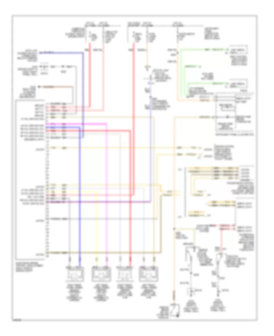
List of elements for Anti-lock Brakes Wiring Diagram for Pontiac GTO 2006:
- (i/p harness, behind driver information switch) s253
- A/t
- Abs & tcs control module fuse 25a
- Abs & tcs fuse 10a
- Abs fuse 40a
- Abs off ind
- Abs serial data
- Auxiliary gauges (not used)
- B c1
- Batt1+
- Batt2+
- Battery
- Body control module (bcm) (below right side of dash)
- Brake fluid level switch (in master cylinder reservoir)
- Brake/ park brake warning ind
- C1 a
- Computer data lines system
- Data link connector (dlc) (under dash, below steering column)
- Electronic brake control module (ebcm) (right side of engine compt)
- Engine control module (ecm) (left side of engine compt, attached to strut tower)
- G102 (engine compt in right front wheel well)
- G103 (right side of engine, attached to abs bracket)
- Ground
- Hot at all times
- Hot in run or start
- Ign 1 voltage
- Instrument panel cluster (ipc)
- Instrument panel fuse block (below left end of dash)
- Instruments fuse 10a
- Lan sig
- Left front wheel speed sensor (inside the front wheel hub)
- Left rear wheel speed sensor (top left side of differential carrier)
- Lf whl spd sig high
- Lf whl spd sig low
- Lr whl spd sig high
- Lr whl spd sig low
- M/t
- Parking brake switch (in center console)
- Powertrain interface module (pim) (behind knee bolster above i/p fuse block)
- Radio
- Red
- Rf whl spd sig high
- Rf whl spd sig low
- Right front wheel speed sensor (inside the front wheel hub)
- Right rear wheel speed sensor (top right side of differential carrier)
- Rr whl spd sig high
- Rr whl spd sig low
- S228
- S229
- S242
- S250 (i/p harness, right side of passenger air bag module)
- S263 (1910 mm from c200)
- S293
- Serial data
- Sp100
- Stop lamp sw sig
- Stop lamp switch (on top of brake pedal support)
- Stop lamps fuse 15a
- Tan
- Traction control switch (behind the power window switches)
- Transmission control module (tcm) (driver's side kick panel, behind hinge pillar trim)
- Uart serial data
- Underhood fuse block (on right side of engine compt)
 Čeština
 Dansk
Dansk Deutsch
 Ελληνικά
 English
 Español
 Suomi
Suomi Français
 Français
 עברית
עברית Hrvatski
 Magyar
 Italiano
 日本語
日本語 한국어
한국어 Nederlands
 Polski
 Português
 Português
 Română
 Русский
 Slovenčina
 Slovenščina
 Svenska
 Türkçe
 中文 (中国)
 English