ANTI-LOCK BRAKES
Anti-lock Brakes Wiring Diagram for Scion xD 2013
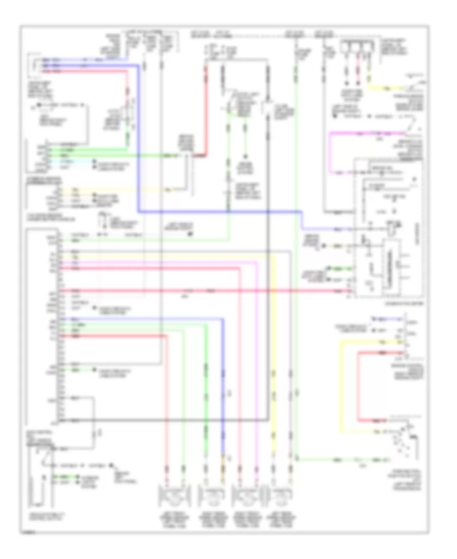
List of elements for Anti-lock Brakes Wiring Diagram for Scion xD 2013:
- (behind center of dash)
- (behind center of dash) j/c f42
- (left side of engine compt) a1
- (left side of engine compt) a2
- +bm
- +bs
- 5v ic
- 5v+b
- A21
- Aa1
- Abs ind
- Abs1/ vsc1 fuse 50a
- Abs2/ vsc2 fuse 30a
- Af3
- Al1
- B12
- B18
- B19
- B21
- B24
- B30
- Bat
- Brake fluid level warning switch (brake fluid reservoir)
- Brake ind
- C19
- Ca1
- Can controller
- Can i/f
- Canh
- Canl
- Combination meter
- Computer data lines system
- Cpu
- Cruise control system
- Csw
- Ecu b fuse 7.5a
- Ecu ig fuse 10a
- Engine control module (right rear of engine compt)
- Engine room r/b (left side of engine compt)
- Ess
- F1 (behind left kick panel)
- F38
- F41
- F42
- Fl+
- Fl-
- Fr+
- Fr-
- Gauge fuse 10a
- Gnd
- Gnd1
- Gnd2
- H12
- Hot at all times
- Hot in on or start
- I/f
- Ig1
- Instrument panel j/b (behind left end of dash)
- Interior lights system
- J/b 6 (behind right kick panel)
- J/c a26 (left side of engine compt)
- J/c f41 & f42 (behind center of dash)
- Led driver
- Left front speed sensor (left front wheel hub)
- Left rear speed sensor (left rear wheel hub)
- Main body ecu canh
- Met fuse 7.5a
- Park/neutral position switch (a/t) (left rear of transmission)
- Parking brake switch (base of park brake lever)
- Pkb
- Pnk
- Red
- Right front speed sensor (right front wheel hub)
- Right rear speed sensor (right rear wheel hub)
- Rl+
- Rl-
- Rr+
- Rr-
- Skid control ecu (left side of engine compt)
- Slip ind
- Sp1
- Steering sensor (steering column)
- Stop fuse 10a
- Stop light switch (bracket, above brake pedal)
- Stp
- Tan
- Vehicle stability control switch
- Vsc off ind
- Yaw rate sensor (under center console)
- Zl1
- Zl2
 Čeština
 Dansk
Dansk Deutsch
 Ελληνικά
 English
 Español
 Suomi
Suomi Français
 Français
 עברית
עברית Hrvatski
 Magyar
 Italiano
 日本語
日本語 한국어
한국어 Nederlands
 Polski
 Português
 Português
 Română
 Русский
 Slovenčina
 Slovenščina
 Svenska
 Türkçe
 中文 (中国)
 English