ANTI-LOCK BRAKES
Anti-lock Brakes Wiring Diagram for Subaru Baja Turbo 2005
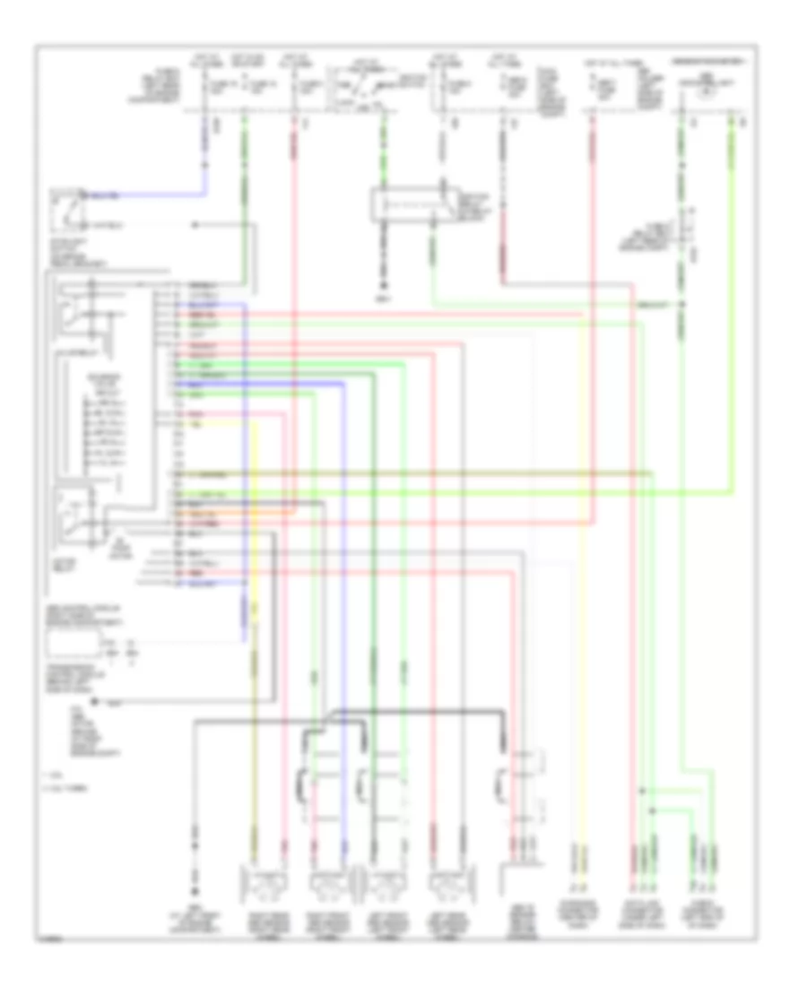
List of elements for Anti-lock Brakes Wiring Diagram for Subaru Baja Turbo 2005:
- 2.5l
- 2.5l turbo
- Abs "g" sensor (below center console)
- Abs control module (right side of engine compartment)
- Abs indicator light
- Acc
- B152
- B158
- B54
- Check connector (left end of of dash)
- Combination meter
- Data link connector (under left side of dash)
- Diagnosis connector (center of dash)
- F37
- F41
- F68
- F73 abs motor ground (at right side of engine compt)
- Fl in
- Fl out
- Fr in
- Fr out
- Fuse & relay box (left rear of engine compartment)
- Fuse & relay box (left rear of engine compt)
- Fuse 16 20a
- Fuse 18 15a
- Fuse 5 15a
- Fuse 8 30a
- Gb-2 (at left front of engine compartment)
- Gb-3
- Hot at all times
- Hot in on or start
- I10
- I12
- Ignition relay (in relay block)
- Ignition switch
- Left front abs sensor (left front wheel)
- Left rear abs sensor (left rear wheel)
- Lock off
- Main fuse box (left side of engine compt)
- Motor relay
- Nca
- Pnk
- Pump motor
- Red
- Right front abs sensor (right front wheel)
- Right rear abs sensor (right rear wheel)
- Rl in
- Rl out
- Rr in
- Rr out
- Sbf holder (left side of engine compt)
- Sbf-5 fuse 30a
- Sbf-7 fuse 30a
- Solenoid valve
- Start
- Stoplight switch (on brake pedal bracket)
- Transmission control module (behind left side of dash)
- Valve relay
 Čeština
 Dansk
Dansk Deutsch
 Ελληνικά
 English
 Español
 Suomi
Suomi Français
 Français
 עברית
עברית Hrvatski
 Magyar
 Italiano
 日本語
日本語 한국어
한국어 Nederlands
 Polski
 Português
 Português
 Română
 Русский
 Slovenčina
 Slovenščina
 Svenska
 Türkçe
 中文 (中国)
 English