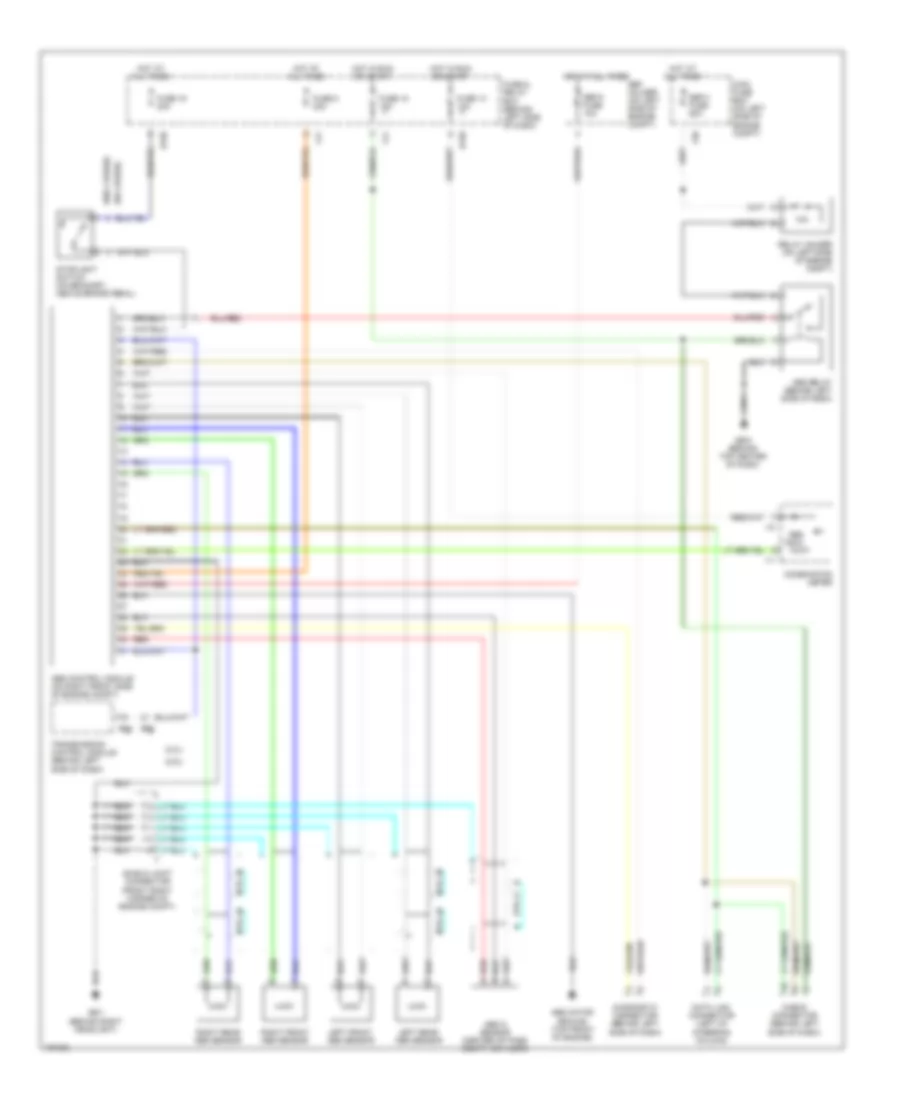
ANTI-LOCK BRAKES
Anti-lock Brake Wiring Diagrams for Subaru Impreza TS 2002
List of elements for Anti-lock Brake Wiring Diagrams for Subaru Impreza TS 2002:
- (2.0l)
- (2.5l)
- (w/ cruise)
- (w/o cruise)
- 10a
- Abs control module (on right front side of engine compt)
- Abs g sensor (center of pass compt, on floor)
- Abs indic
- Abs motor ground (top front of engine)
- Abs relay (behind left side of dash)
- B158
- B54
- B55
- Check connector (behind left side of dash)
- Combination meter
- Data link connector (left of steering column)
- Diagnostic connector (behind left side of dash)
- F38
- F41
- Fuse & relay box (behind left side of dash)
- Fuse 13 10a
- Fuse 16 20a
- Fuse 18 15a
- Fuse 8 20a
- Gb-1 (behind right headlight)
- Gb-5 (behind top center of dash)
- Hot at all times
- Hot in run or start
- I10
- I11
- Left front abs sensor
- Left rear abs sensor
- Main fuse box (on left side of engine compt)
- Red
- Relay holder (on left side of engine compt)
- Right front abs sensor
- Right rear abs sensor
- Sbf holder (on left side of engine compt)
- Sbf-4 fuse 50a
- Sbf-8 fuse 10a
- Shield joint connector (front right corner of engine compt)
- Stoplight switch (on bracket, above brake pedal)
- Transmission control module (behind left side of dash)
 Čeština
 Deutsch
 Ελληνικά
 English
 English
 Español
 Suomi
Suomi Français
 Français
 עברית
עברית Hrvatski
 Magyar
 Italiano
 日本語
日本語 한국어
한국어 Nederlands
 Polski
 Português
 Português
 Română
 Русский
 Slovenčina
 Slovenščina
 Svenska
 Türkçe
 中文 (中国)
 Dansk
Dansk