
 Čeština
 Dansk
Dansk Deutsch
 Ελληνικά
 English
 Español
 Suomi
Suomi Français
 Français
 עברית
עברית Hrvatski
 Magyar
 Italiano
 日本語
日本語 한국어
한국어 Nederlands
 Polski
 Português
 Português
 Română
 Русский
 Slovenčina
 Slovenščina
 Svenska
 Türkçe
 中文 (中国)

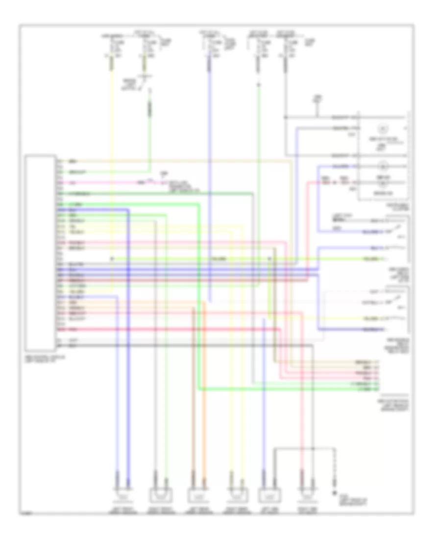
ANTI-LOCK BRAKES
Anti-lock Brake Wiring Diagrams for Suzuki Swift 1996
List of elements for Anti-lock Brake Wiring Diagrams for Suzuki Swift 1996:

AIR CONDITIONINGANTI-LOCK BRAKESCOMPUTER DATA LINESHEADLIGHTSCOOLING FANDEFOGGERSENGINE PERFORMANCEHORNEXTERIOR LIGHTSINTERIOR LIGHTSPOWER DISTRIBUTIONINSTRUMENT CLUSTERSTARTING/CHARGINGPOWER DOOR LOCKSGROUND DISTRIBUTIONRADIOSHIFT INTERLOCKSWARNING SYSTEMSTRANSMISSIONSUPPLEMENTAL RESTRAINTSWIPER/WASHER