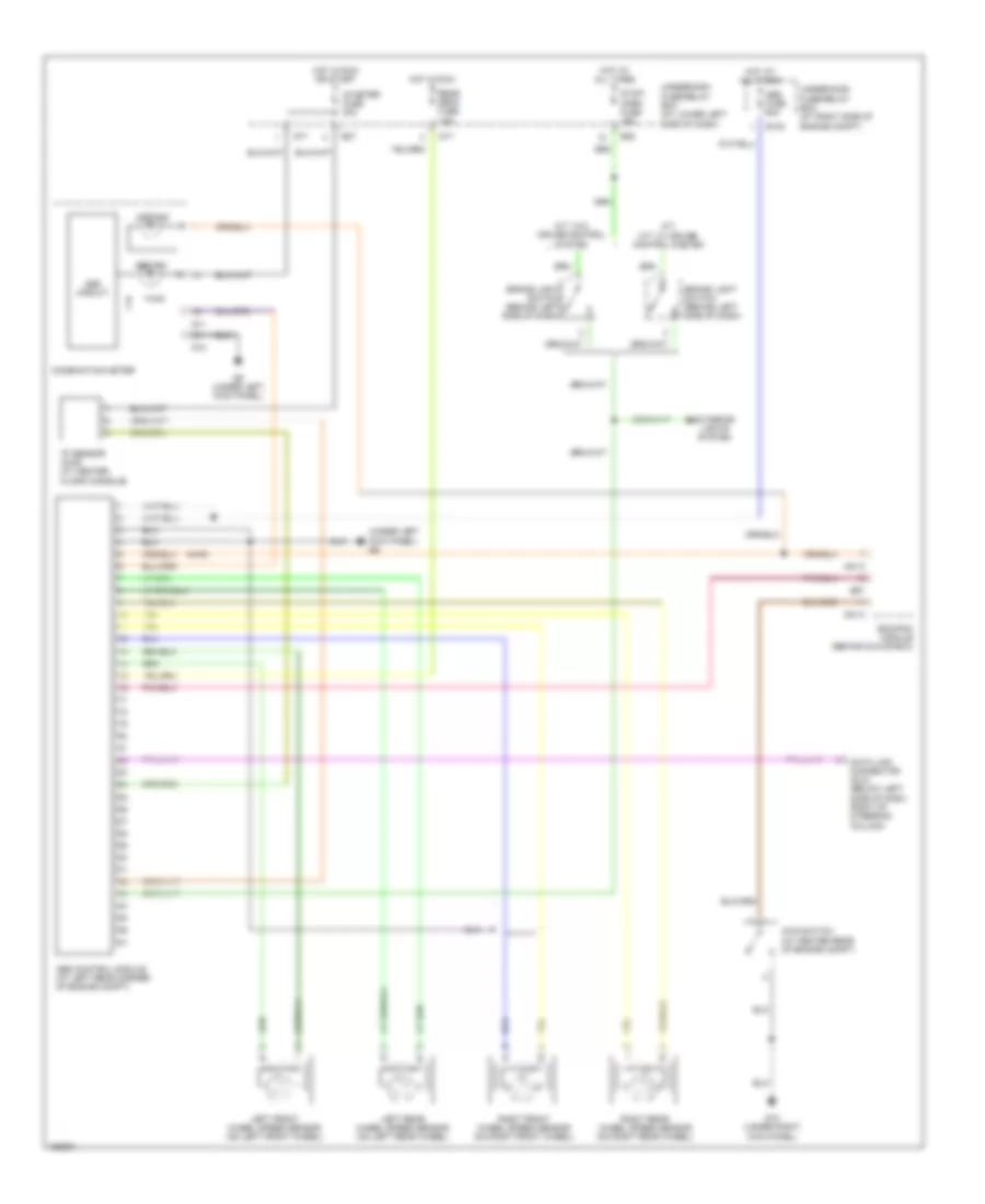
ANTI-LOCK BRAKES
Anti-lock Brakes Wiring Diagram for Suzuki Vitara 2004
List of elements for Anti-lock Brakes Wiring Diagram for Suzuki Vitara 2004:
- "g" sensor (4wd) (at center floor console)
- (4wd)
- (under left kick panel) g9
- 4wd ind
- 4wd switch (at center rear of engine compt)
- A/t, m/t: w/ cruise control system
- Abs circuit
- Abs control module (at left rear corner of engine compt)
- Abs fuse 50a
- Abs ind
- Brake light switch (behind left side of dash)
- C51-2
- Combination meter
- Data link connector (dlc) (below left side of dash, right of steering column)
- E124
- E27
- E28
- E61
- Ecm/pcm module (behind glove box)
- Exterior lights system
- G10 (under right kick panel)
- G11
- G12
- G17
- G9 (under left kick panel)
- Hot at all times
- Hot in run
- Hot in run or start
- Ig meter fuse 20a
- Left front wheel speed sensor (on left front wheel)
- Left rear wheel speed sensor (on left rear wheel)
- M/t: w/o cruise control system
- Rear defg fuse 15a
- Right front wheel speed sensor (on right front wheel)
- Right rear wheel speed sensor (on right rear wheel)
- Stop/ horn fuse 15a
- Underdash fuse/relay box (at lower left side of dash)
- Underhood fuse/relay box (at right side of engine compt)
 Čeština
 Dansk
Dansk Deutsch
 Ελληνικά
 English
 English
 Español
 Suomi
Suomi Français
 Français
 עברית
עברית Hrvatski
 Magyar
 Italiano
 日本語
日本語 한국어
한국어 Nederlands
 Polski
 Português
 Română
 Русский
 Slovenčina
 Slovenščina
 Svenska
 Türkçe
 中文 (中国)
 Português