ANTI-LOCK BRAKES
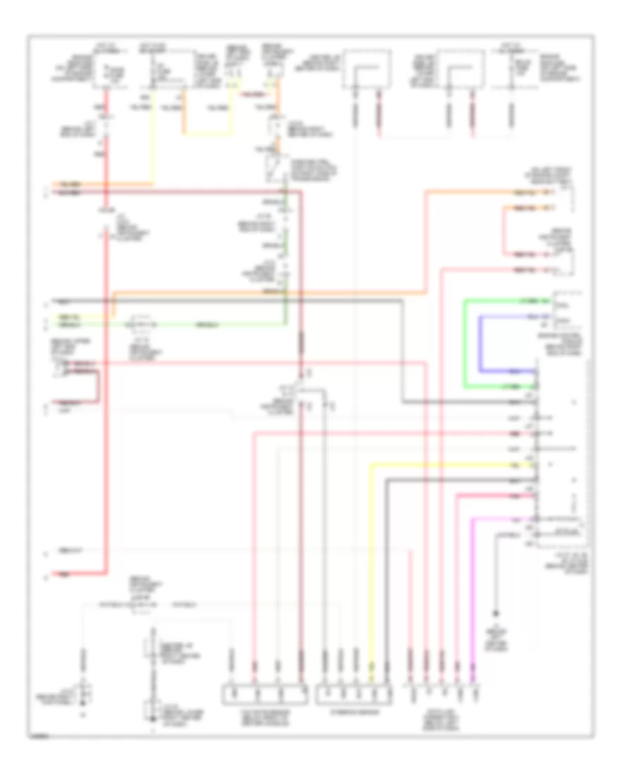
Anti-lock Brakes Wiring Diagram (1 of 3) for Toyota 4Runner SR5 2006
 https://portal-diagnostov.com/license.html
Automotive Electricians Portal FZCO
Automotive Electricians Portal FZCO
https://portal-diagnostov.com/license.html
https://portal-diagnostov.com/license.html
Automotive Electricians Portal FZCO
Automotive Electricians Portal FZCO
List of elements for Anti-lock Brakes Wiring Diagram (1 of 3) for Toyota 4Runner SR5 2006:
- (2wd)
- (4wd)
- (behind upper left end of dash) j/c 4
- +bm1
- +bm2
- +bs
- 4.7l
- Abs mtr fuse 40a
- Abs sol fuse 30a
- Auto lsd switch (2wd)
- B j3
- Brake fluid level warning switch (on brake fluid reservoir)
- Brl
- Canh
- Canl
- Center j/b (behind right center of dash)
- Csw
- D/g
- Downhill assist control switch (4wd)
- Driver side j/b (behind lower left end of dash)
- Ea (on right front inner fender)
- Eb (on left front inner fender)
- Engine room r/b (on left side of engine compt)
- Exi
- Exi3
- Exi4
- Fl+
- Fl-
- Flo
- Fr+
- Fr-
- Fro
- Gnd1
- Gnd2
- Gnd3
- Hdcs
- Hdcw
- Hot at all times
- Hot in or or start
- Ig1
- Ig2
- Ign fuse 10a
- Ind
- Infr
- J/c 14 & 15 (behind instrument cluster) a
- J/c 2 & 3 (on left front of engine compt, near battery)
- J/c 37 (behind right kick panel)
- J/c 4 (behind upper left end of dash)
- J/c 5 (behind right kick panel)
- J14
- J15
- J2 b
- Lbl
- Neo
- Parking brake switch (behind upper left end of dash)
- Pkb
- Pnk
- Red
- Right front abs speed sensor (on right front spindle/hub assembly)
- Rl+
- Rl-
- Rr+
- Rr-
- S15
- S28
- S29
- Skid control ecu w/ actuator (left rear of engine compt)
- Sp1
- Stop fuse 10a
- Stop light switch (behind left side of dash, above brake pedal)
- Stop lp ctrl relay
- Stp
- Stp2
- Stpo
- Suspension control ecu (w/ electric modulated air suspension) (behind left end of dash, near base of ``a" pillar)
- Vscw
- Wfse
Anti-lock Brakes Wiring Diagram (2 of 3) for Toyota 4Runner SR5 2006
List of elements for Anti-lock Brakes Wiring Diagram (2 of 3) for Toyota 4Runner SR5 2006:
- (4wd)
- (4wd) (2wd)
- (behind instrument cluster) j/c 20 & 21
- (behind right end of dash) j/c 29 & 30
- (behind right end of dash) j/c 31 & 32
- (left side of dash) vsc warning buzzer
- (on left front of engine compt, near battery) j/c 1
- (or pnk)
- 2wd
- 4.0l 4wd
- 4wd
- 4wd control ecu (4wd) (behind lower right end of dash)
- Abs ind
- Add
- Add actuator (on right front of engine)
- Bo (on left "d" pillar)
- Brake ind
- C10
- C11
- Cdl
- Combination meter
- Dac ind
- Driver side j/b (behind lower left end of dash)
- E12
- Ecu-ig fuse 10a
- Ed (4.7l) (on left cylinder head)
- Ee (4.0l) (on rear of right cylinder head)
- F10
- Gauge fuse 7.5a
- Hot in on or start
- Ind2
- J/c 20 (behind instru- ment cluster)
- J/c 28 (behind right side of dash, near firewall grommet)
- J/c 4 (behind upper left end of dash)
- J20
- J21
- J29
- J30
- J31
- J32
- Left front abs speed sensor (on left front spindle/hub assembly)
- Left rear abs speed sensor (on left side of rear axle)
- Pnk
- Red
- Right rear abs speed sensor (on right side of rear axle)
- Slip ind
- Speedometer
- Transfer shift actuator (on transmission)
- Vsc off ind trac off ind
- Vsc trac ind
Anti-lock Brakes Wiring Diagram (3 of 3) for Toyota 4Runner SR5 2006
List of elements for Anti-lock Brakes Wiring Diagram (3 of 3) for Toyota 4Runner SR5 2006:
- (behind
- (behind instrument cluster)
- (behind instrument cluster) j/c 20
- (behind left end of dash) j/c 7
- (behind right end of dash)
- (behind upper left end of dash) j/c 4
- (on left front of engine compt, near battery) j/c 1
- Bat
- Canh
- Canl
- Center j/b (behind right center of dash)
- Cluster)
- Data link connector 3 (below left side of dash)
- Dome fuse 10a
- Driver side j/b (behind lower left end of dash)
- E20
- Ecu-b fuse 10a
- Engine control module (behind right end of dash)
- Engine room r/b (on left side of engine compartment)
- Ess
- Gnd
- Hot at all times
- Hot in on or start
- Ig1
- Ig1 fuse 15a
- Ih (behind left center of dash)
- Instrument
- J/c 12 & 13
- J/c 15
- J/c 18
- J/c 24 (behind lower right center of dash)
- J/c 25 (behind right center of dash)
- J/c 35
- J/c 47, 48, 49, 50, 51 & 52 (behind center of dash)
- J/c 5 (behind right kick panel)
- J/c 7 (behind left end of dash)
- J/c 8 & 9 (behind instrument cluster)
- J/c 8 (behind instrument cluster)
- J12
- J13
- J47
- J48
- J49
- J50
- J51
- J52
- Park/neutral position switch (on right side of transmission)
- Pnk
- Red
- Sil
- St-plug
- Steering sensor
- Wfse
- Yaw rate sensor (below front of center console)

 Čeština
 Dansk
Dansk Deutsch
 Ελληνικά
 English
 Español
 Suomi
Suomi Français
 Français
 עברית
עברית Hrvatski
 Magyar
 Italiano
 日本語
日本語 한국어
한국어 Nederlands
 Polski
 Português
 Português
 Română
 Русский
 Slovenčina
 Slovenščina
 Svenska
 Türkçe
 中文 (中国)