Čeština
 Dansk
Dansk Deutsch
 Ελληνικά
 English
 Español
 Suomi
Suomi Français
 Français
 עברית
עברית Hrvatski
 Magyar
 Italiano
 日本語
日本語 한국어
한국어 Nederlands
 Polski
 Português
 Português
 Română
 Русский
 Slovenčina
 Slovenščina
 Svenska
 Türkçe
 中文 (中国)

ANTI-LOCK BRAKES
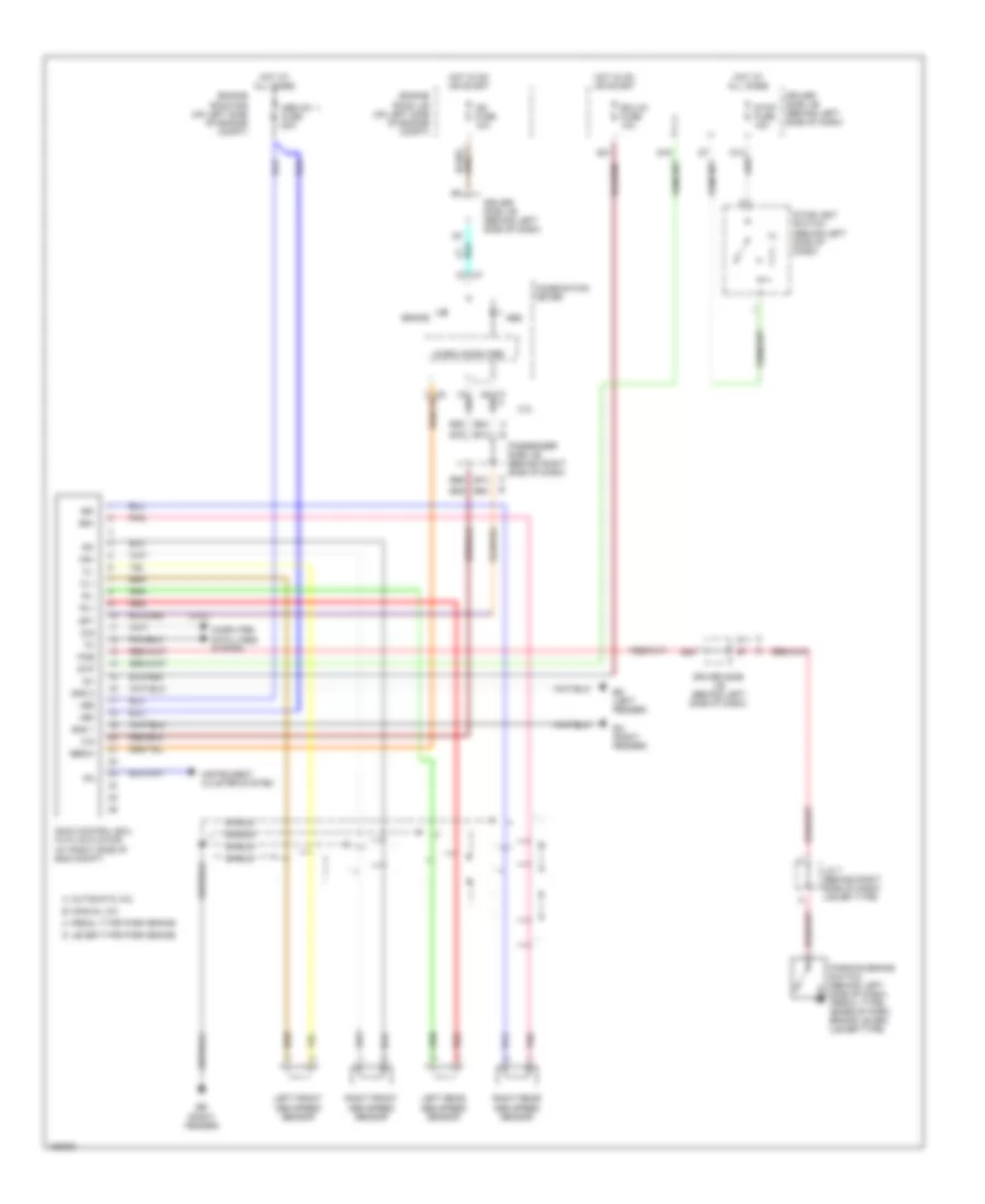
Anti-lock Brake Wiring Diagrams, Japan Production for Toyota Camry SE 2002


List of elements for Anti-lock Brake Wiring Diagrams, Japan Production for Toyota Camry SE 2002:
Anti-lock Brake Wiring Diagrams, USA Production for Toyota Camry SE 2002
List of elements for Anti-lock Brake Wiring Diagrams, USA Production for Toyota Camry SE 2002:
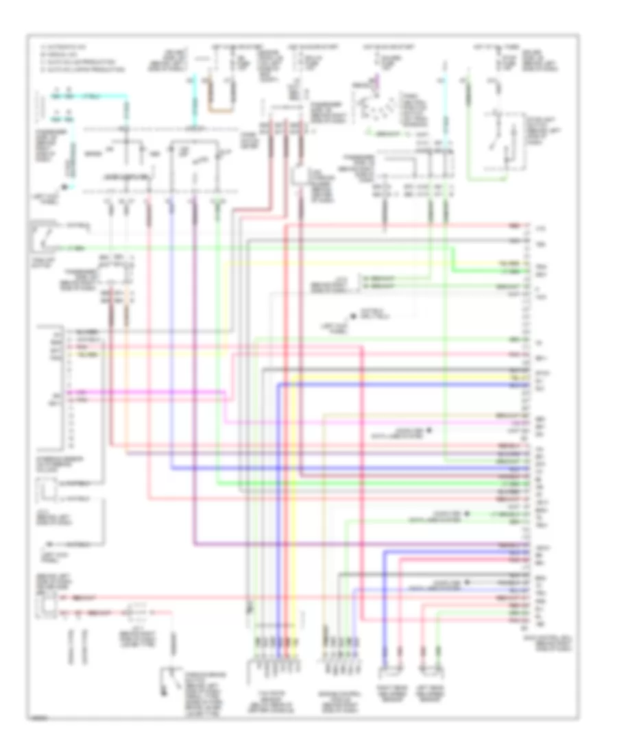
Anti-lock Brake Wiring Diagrams, with VSC (1 of 2) for Toyota Camry SE 2002
List of elements for Anti-lock Brake Wiring Diagrams, with VSC (1 of 2) for Toyota Camry SE 2002:
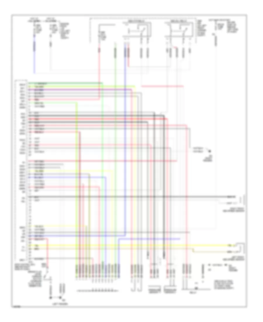
Anti-lock Brake Wiring Diagrams, with VSC (2 of 2) for Toyota Camry SE 2002
List of elements for Anti-lock Brake Wiring Diagrams, with VSC (2 of 2) for Toyota Camry SE 2002: