ANTI-LOCK BRAKES
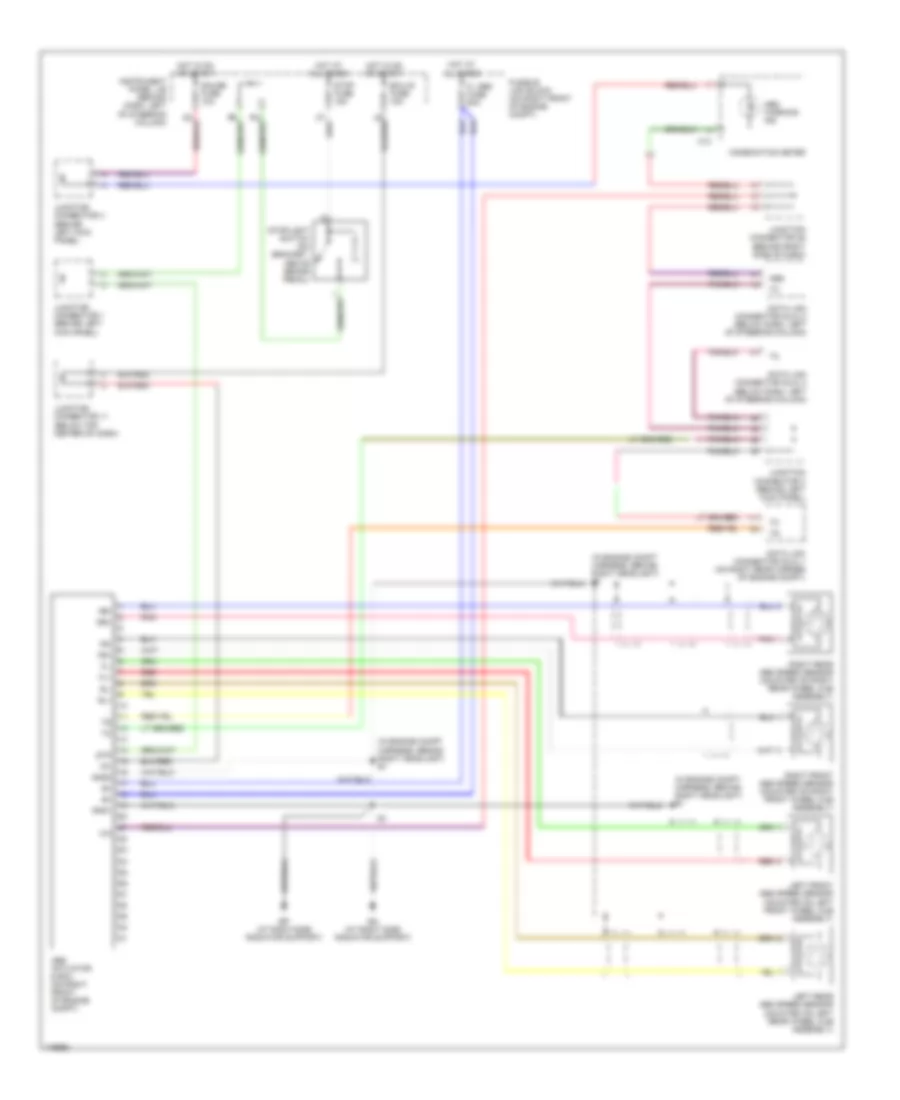
Anti-lock Brakes Wiring Diagram, with Traction Control for Toyota Camry Solara SLE 2003
 https://portal-diagnostov.com/license.html
Automotive Electricians Portal FZCO
Automotive Electricians Portal FZCO
https://portal-diagnostov.com/license.html
https://portal-diagnostov.com/license.html
Automotive Electricians Portal FZCO
Automotive Electricians Portal FZCO
List of elements for Anti-lock Brakes Wiring Diagram, with Traction Control for Toyota Camry Solara SLE 2003:
- (at left dash brace)
- (at right side radiator support) ea
- (in dash harness, at right side of dash)
- A j7
- A22
- A23
- A24
- Abs
- Abs & traction actuator (3.0l: on right front of engine compartment)
- Abs & traction ecu (behind right side of dash)
- Abs ind
- Abs motor relay
- Abs sol relay
- Ast
- B j24
- B j25
- C11
- C13
- Combination meter
- Csw
- Data link connector (dlc) 1 (on right rear corner of engine compt)
- Data link connector (dlc) 2 (below dash, left of steering column)
- Data link connector (dlc) 3 (below dash, left of steering column)
- E10
- Ecu-ig fuse 15a
- Efi+
- Efi-
- Engine control module (behind right side of dash)
- Engine room r/b 3 (on right front of engine compt)
- Ep (at right side radiator support)
- Fl abs fuse 60a
- Fl+
- Fl-
- Fr+
- Fr-
- Gauge fuse 10a
- Gnd1
- Gnd2
- Gnd3
- Hot at all times
- Hot in on or start
- Ig1
- Ind
- Instrument panel j/b (behind dash, left of steering column)
- J/c 1 (behind left kick panel)
- J/c 10 (behind center of dash)
- J/c 11 (below top center of dash)
- J/c 24, j/c 25 (behind right side of dash)
- J/c 26 (behind right side of dash)
- J/c 3 (behind left kick panel)
- J/c 4 (behind left kick panel)
- J/c 7, j/c 8 (behind left side of dash)
- J24 b
- Left front abs speed sensor (mounted on left front wheel hub assembly)
- Left rear abs speed sensor (mounted on left rear wheel hub assembly)
- Neo
- Pnk
- Red
- Right front abs speed sensor (mounted on right front wheel hub assembly)
- Right rear abs speed sensor (mounted on right rear wheel hub assembly)
- Rl+
- Rl-
- Rr+
- Rr-
- Sflh
- Sflr
- Sfrh
- Sfrr
- Slip ind
- Smc1
- Smc2
- Src1
- Src2
- Srlh
- Srlr
- Srrh
- Srrr
- Stop fuse 15a
- Stop- light switch (on bracket, above brake pedal)
- Stp
- Throttle position sensor (3.0l: on throttle body assembly)
- Trac off ind
- Traction off switch
- Trc
- Trc+
- Trc-
Anti-lock Brakes Wiring Diagram, without Traction Control for Toyota Camry Solara SLE 2003
List of elements for Anti-lock Brakes Wiring Diagram, without Traction Control for Toyota Camry Solara SLE 2003:
- (behind right side of dash)
- (in engine compt harness, behind right headlight) e1
- Abs
- Abs actuator & ecu (on right front of engine compt)
- Abs warning ind
- C13
- Combination meter
- Connector 26
- Data link connector (dlc) 1 (on right rear corner of engine compt)
- Data link connector (dlc) 2 (below dash, left of steering column)
- Data link connector (dlc) 3 (below dash, left of steering column)
- Ea (at right side radiator support)
- Ecu-ig fuse 15a
- Ep (at right side radiator support)
- Fl abs fuse 60a
- Fl+
- Fl-
- Fr+
- Fr-
- Fusible link block (on right front of engine compt)
- Gauge fuse 10a
- Gnd1
- Gnd2
- Hot at all times
- Hot in on or start
- Ig1
- Instrument panel j/b (behind dash, left of steering column)
- Junction
- Junction connector 1 (behind left kick panel)
- Junction connector 11 (below top center of dash)
- Junction connector 3 (behind left kick panel)
- Junction connector 4 (behind left kick panel)
- Left front abs speed sensor (mounted on left front wheel hub assembly)
- Left rear abs speed sensor (mounted on left rear wheel hub assembly)
- Pnk
- Red
- Right front abs speed sensor (mounted on right front wheel hub assembly)
- Right rear abs speed sensor (mounted on right rear wheel hub assembly)
- Rl+
- Rl-
- Rr+
- Rr-
- Stop fuse 15a
- Stoplight switch (on bracket, above brake pedal)
- Stp

 Čeština
 Dansk
Dansk Deutsch
 Ελληνικά
 English
 Español
 Suomi
Suomi Français
 Français
 עברית
עברית Hrvatski
 Magyar
 Italiano
 日本語
日本語 한국어
한국어 Nederlands
 Polski
 Português
 Português
 Română
 Русский
 Slovenčina
 Slovenščina
 Svenska
 Türkçe
 中文 (中国)