ANTI-LOCK BRAKES
Anti-lock Brake Wiring Diagrams for Toyota Celica GT 1995
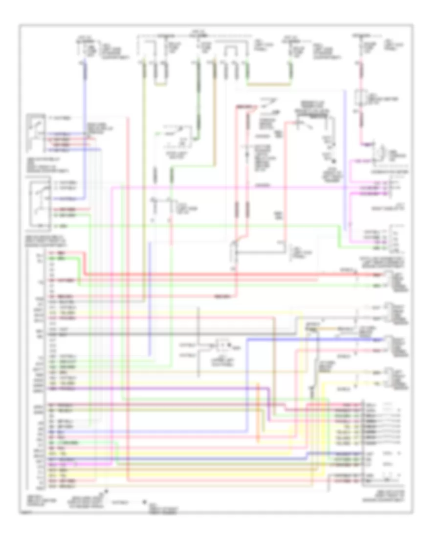
List of elements for Anti-lock Brake Wiring Diagrams for Toyota Celica GT 1995:
- (brake fluid reservoir) brake fluid level warning switch
- (eng harn, above grille opening) e1
- (i/p harn, behind radio)
- A10
- A11
- A12
- A13
- A14
- A15
- A16
- A17
- A18
- A19
- A20
- A21
- A22
- A23
- A24
- A25
- A26
- Abs actuator (right front of engine compartment)
- Abs ecu (below center console)
- Abs fuse 50a
- Abs motor relay (r/b, right front of engine compartment)
- Abs solenoid relay (r/b 5, right front of engine compartment)
- Abs warning ind
- Ast
- B10
- B11
- B12
- B13
- B14
- B15
- B16
- Batt
- C10
- Canada
- Combination meter
- Data link connector 1 (left rear corner of engine compartment)
- Daytime running lights relay main (behind center of i/p)
- E2 (eng harn, right side of eng compt, on fender apron)
- Ecu-b fuse 15a
- Ecu-ig fuse 15a
- Fl+
- Fl-
- Fr+
- Fr-
- Fss
- G100 (front of left front fender)
- G101 (front of right front fender)
- G200
- Gauge fuse 10a
- Gnd1
- Gnd2
- Grd
- Hot at all times
- Hot in on
- I17
- Ig1
- J/b 1 (left kick panel)
- J/b 2 (left side of engine compartment)
- J/b 3 (behind center of i/p)
- J/c 1 (upper left kick panel)
- J/c 2 (left side of i/p)
- J/c 7 (right side of i/p)
- Left front abs speed sensor
- Left rear abs speed sensor
- Parking brake switch
- Pkb
- Pnk
- R/b 2 (left side of engine compartment)
- Red
- Right front abs speed sensor
- Right rear abs speed sensor
- Rl+
- Rl-
- Rr+
- Rr-
- Rss
- Sflh
- Sflr
- Sfrh
- Sfrr
- Shield
- Srlh
- Srlr
- Srrh
- Srrr
- Stop fuse 15a
- Stop light switch
- Stp
 Čeština
 Dansk
Dansk Deutsch
 Ελληνικά
 English
 Español
 Suomi
Suomi Français
 Français
 עברית
עברית Hrvatski
 Magyar
 Italiano
 日本語
日本語 한국어
한국어 Nederlands
 Polski
 Português
 Português
 Română
 Русский
 Slovenčina
 Slovenščina
 Svenska
 Türkçe
 中文 (中国)
 English