ANTI-LOCK BRAKES
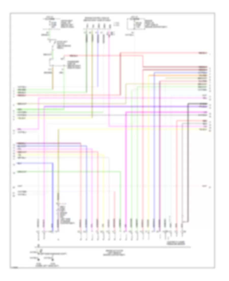
Anti-lock Brake Wiring Diagrams, with VSC (1 of 3) for Toyota Highlander Limited 2001
 https://portal-diagnostov.com/license.html
Automotive Electricians Portal FZCO
Automotive Electricians Portal FZCO
https://portal-diagnostov.com/license.html
https://portal-diagnostov.com/license.html
Automotive Electricians Portal FZCO
Automotive Electricians Portal FZCO
List of elements for Anti-lock Brake Wiring Diagrams, with VSC (1 of 3) for Toyota Highlander Limited 2001:
- +bi
- +bo
- A12
- Abs
- Abs 1 fuse 40a
- Abs 2 fuse 40a
- Abs r/b (on left rear of engine compt)
- Abs sol relay
- Brake
- Brake warning switch (on master cylinder assembly)
- Brl
- C11
- C12
- Combination meter
- Data link connector 3 (under left side of dash)
- Eng+
- Engine room r/b 1 (on left side of engine compt)
- Fl+
- Fl-
- Fr+
- Fr-
- Fusible link block (on left side of engine compt)
- G101
- Gnd1
- Gnd2
- Hot at all times
- Hot in run and start
- Ig1
- Ign fuse 7.5a
- Ind
- Instrument panel j/b (behind left side of dash)
- J/c 4 (right side of engine compartment)
- J/c 6 (left side of dash behind instrument cluster)
- Lbl
- Left front abs speed sensor
- Left rear abs speed sensor
- Mr2
- Parking brake switch (on base of park brake lever)
- Passengers side j/b (behind right side of dash)
- Passengers side j/b (behind right side of dash)
- Pkb
- R1+
- R2+
- Right front abs speed sensor
- Right rear abs speed sensor
- Rl+
- Rl-
- Rr+
- Rr-
- S11
- S12
- Sflh
- Sflr
- Sil
- Skid control ecu (above instrument panel j/b)
- Skid control relay
- Slip
- Sp1
- Src1
- Src2
- Srm1
- Srm2
- Srrh
- Srrr
- Stp
- Trac off
- Trc+
- Trc-
- Vsc
- Vscw
Anti-lock Brake Wiring Diagrams, with VSC (2 of 3) for Toyota Highlander Limited 2001
 https://portal-diagnostov.com/license.html
Automotive Electricians Portal FZCO
Automotive Electricians Portal FZCO
https://portal-diagnostov.com/license.html
https://portal-diagnostov.com/license.html
Automotive Electricians Portal FZCO
Automotive Electricians Portal FZCOList of elements for Anti-lock Brake Wiring Diagrams, with VSC (2 of 3) for Toyota Highlander Limited 2001:
- (under left headlight)
- 2.4l
- 3.0l
- A11
- Abs 3 fuse 7.5a engine room r/b (left side of engine compartment)
- Brake actuator (left rear of engine compartment)
- E5 e6
- Ecu-b fuse 7.5a
- Eng+
- Engine control module (behind right side of dash)
- Engine room j/b (left side of engine compartment)
- G106
- Hot at all times
- Instrument panel j/b (behind left side of dash)
- Master cylinder pressure sensor
- Neo
- Passenger side j/b (behind right side of dash)
- Red
- Shield
- Stop fuse 20a
- Stoplight switch (above brake pedal)
- Trc+
- Trc-
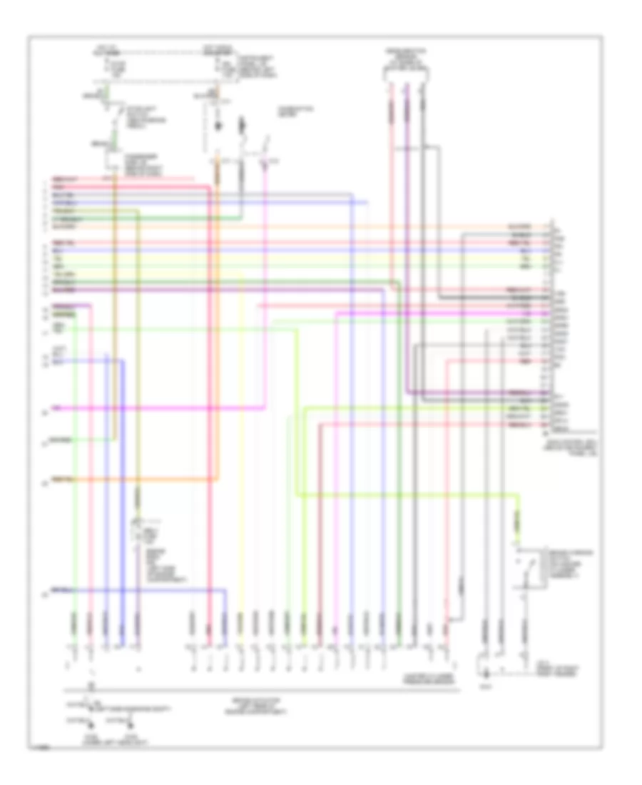
Anti-lock Brake Wiring Diagrams, with VSC (3 of 3) for Toyota Highlander Limited 2001
 https://portal-diagnostov.com/license.html
Automotive Electricians Portal FZCO
Automotive Electricians Portal FZCO
https://portal-diagnostov.com/license.html
https://portal-diagnostov.com/license.html
Automotive Electricians Portal FZCO
Automotive Electricians Portal FZCOList of elements for Anti-lock Brake Wiring Diagrams, with VSC (3 of 3) for Toyota Highlander Limited 2001:
- 1mz-fe
- 2az-fe
- 2wd
- A/t indicator switch (left side of transmission)
- Ast
- Bat
- Brake pedal load sensing switch (above brake pedal)
- C11
- Center j/b (behind upper center of dash)
- Cruise control system
- Csw
- D/g
- D10
- Deceleration sensor (at base of shifter lever
- Ecu-ig fuse 15a
- Ess
- Fss
- Fsw+
- Fsw-
- G106
- G203 (upper right kick panel)
- G206 (right instriment panel brace)
- Ggnd
- Gl1
- Gl2
- Gnd3
- Gnd4
- Gss
- Gyaw
- Hot in run and start
- Ig1 fuse 7.5a
- Instrument panel j/b (behind left side of dash)
- J/c 2 (behind left headlamp)
- J/c 6 (left side of dash behind instrument cluster)
- J/c 8 (behind right side of dash)
- Neo
- Passenger side j/b (behind right side of dash)
- Pmc
- Red
- S10
- Sfrh
- Sfrr
- Shield
- Skid control ecu (above instrument panel j/b)
- Sm1+
- Sm1-
- Sm2+
- Sm2-
- Srlh
- Srlr
- Ss1+
- Ss1-
- Trac off switch (left side of dash)
- Trig
- Vcm
- Vgs
- Vsc steering sensor (in steering column)
- Vsc warning buzzer (above i/p junction block)
- Vys
- Yaw rate sensor (on rear of vehicle)
- Yaw2
- Yss
Anti-lock Brake Wiring Diagrams, without VSC (1 of 2) for Toyota Highlander Limited 2001
 https://portal-diagnostov.com/license.html
Automotive Electricians Portal FZCO
Automotive Electricians Portal FZCO
https://portal-diagnostov.com/license.html
https://portal-diagnostov.com/license.html
Automotive Electricians Portal FZCO
Automotive Electricians Portal FZCOList of elements for Anti-lock Brake Wiring Diagrams, without VSC (1 of 2) for Toyota Highlander Limited 2001:
- A12
- Abs 1 fuse 25a
- Abs 2 fuse 40a
- Abs mtr relay
- Abs sol relay
- Ast
- Automatic transmission system
- Brl
- D/g
- D10
- Data link connector 3 (under left side of dash)
- Ecu-ig fuse 15a
- Engine room r/b 1 (on left side of engine compt)
- Fusible link block (on left side of engine compt)
- G106
- Gnd3
- Gnd4
- Hot at all times
- Hot in run and start
- Ig1
- Instrument panel j/b (behind left side of dash)
- J/c 2 (under left headlight)
- J/c 6 (left side of dash behind instrument cluster)
- Left front abs speed sensor
- Left rear abs speed sensor
- Mrf
- Parking brake switch (on base of park brake lever)
- Passengers side j/b (behind right side of dash)
- Pkb
- Pnk
- Right front abs speed sensor
- Right rear abs speed sensor
- Rl+
- Rl-
- Rr+
- Rr-
- Sflh
- Sflr
- Sil
- Skid control ecu (above instrument panel j/b)
- Sm1+
- Sm1-
- Sm2+
- Sm2-
- Sp1
- Srrh
- Srrr
- Stp
Anti-lock Brake Wiring Diagrams, without VSC (2 of 2) for Toyota Highlander Limited 2001
 https://portal-diagnostov.com/license.html
Automotive Electricians Portal FZCO
Automotive Electricians Portal FZCO
https://portal-diagnostov.com/license.html
https://portal-diagnostov.com/license.html
Automotive Electricians Portal FZCO
Automotive Electricians Portal FZCOList of elements for Anti-lock Brake Wiring Diagrams, without VSC (2 of 2) for Toyota Highlander Limited 2001:
- (under left headlight)
- A11
- Abs
- Abs 3 fuse 7.5a
- Brake
- Brake actuator (left rear of engine compartment)
- Brake warning switch (on master cylinder assembly)
- C11
- C12
- Combination meter
- Deceleration sensor (at base of shifter lever)
- Engine room r/b (left side of engine compartment)
- Fl+
- Fl-
- Fr+
- Fr-
- Fss
- G101
- G106
- Ggnd
- Gl1
- Gnd1
- Gnd2
- Gss
- Hot at all times
- Hot in run and start
- Ign fuse 7.5a
- Instrument panel j/b (behind left side of dash)
- J/c 4 (front of right front fender)
- Master cylinder pressure sensor
- Passenger side j/b (behind right side of dash)
- Pmc
- Pnk
- Red
- Sfrh
- Sfrr
- Shield
- Skid control ecu (above instrument panel j/b)
- Splh
- Srlr
- Srm1
- Srm2
- Stop fuse 15a
- Stoplight switch (above brake pedal)
- Vcm
- Vgs

 Čeština
 Dansk
Dansk Deutsch
 Ελληνικά
 English
 English
 Español
 Suomi
Suomi Français
 Français
 עברית
עברית Hrvatski
 Magyar
 Italiano
 日本語
日本語 Nederlands
 Polski
 Português
 Português
 Română
 Русский
 Slovenčina
 Slovenščina
 Svenska
 Türkçe
 中文 (中国)
